1TA·3.t4
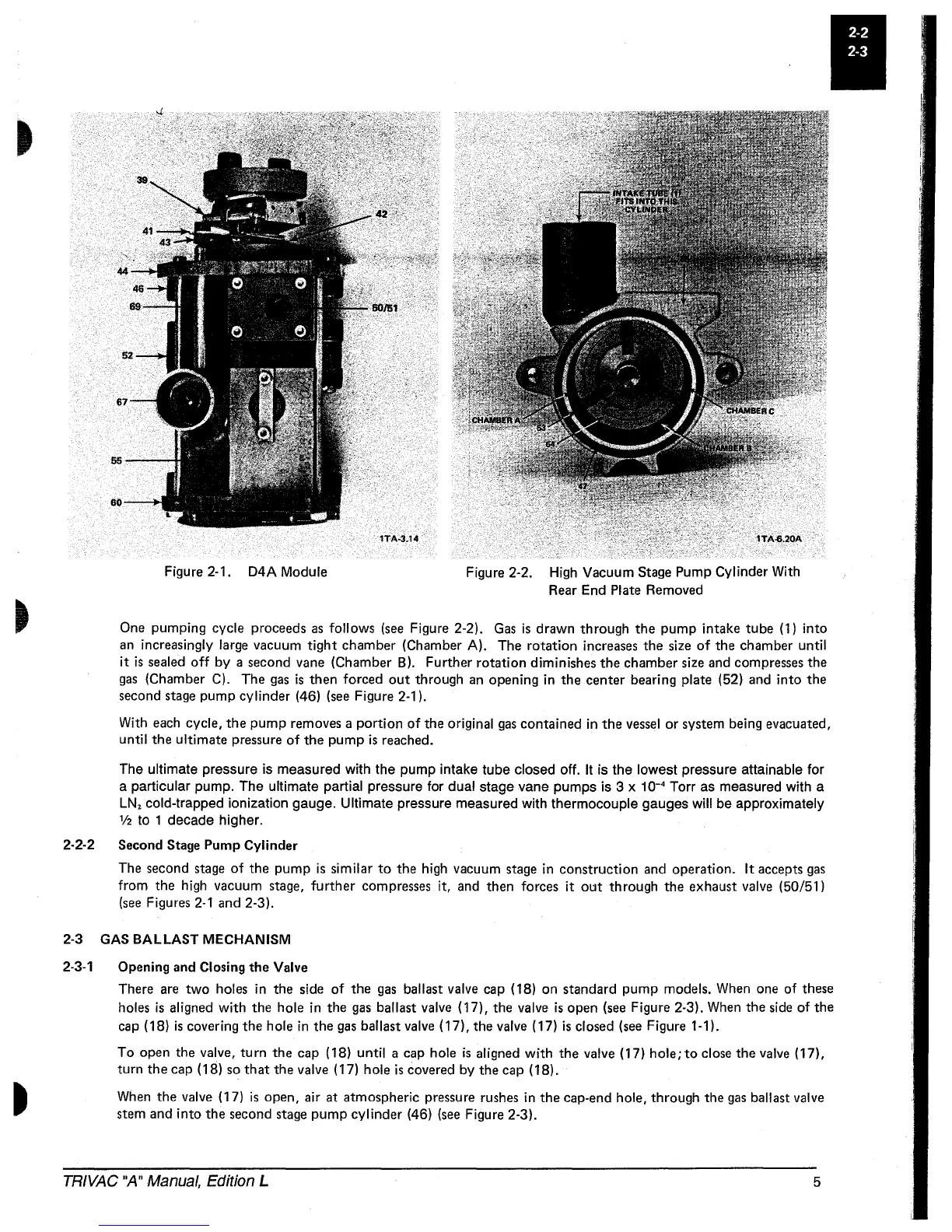
Figure 2·1.
D4A
Module
Figure 2·2. High Vacuum
Stage
Pump Cylinder With
Rear End
Plate Removed
One
pumping cycle proceeds
as
follows
(see
Figure 2-2).
Gas
is
drawn through the pump intake tube (1)
into
an
increasingly large vacuum
tight
chamber (Chamber A). The rotation increases the
size
of
the chamber
until
it
is
sealed
off
by
a second vane (Chamber B). Further rotation diminishes the chamber
size
and
compresses the
gas
(Chamber C). The
gas
is
then forced
out
through
an
opening in the center bearing plate (52)
and
into
the
second
stage
pump cylinder (46)
(see
Figure 2·1).
With
each
cycle, the
pump
removes a
portion
of
the original
gas
contained in the
vessel
or
system being evacuated,
until
the ultimate pressure
of
the pump
is
reached.
The
ultimate pressure is measured with the pump intake tube closed off. It is the lowest pressure attainable for
a
particular pump. The ultimate partial pressure for dual stage vane pumps is 3 x 10-
4
Torr as measured with a
LN
z
cold-trapped ionization gauge. Ultimate pressure measured with thermocouple gauges will be approximately
1/2
to 1 decade higher.
2-2·2 Second Stage Pump Cylinder
The second
stage
of
the pump
is
similar
to
the high vacuum
stage
in construction
and
operation.
It
accepts
gas
from the high vacuum
stage,
further
compresses
it,
and
then forces
it
out
through the exhaust valve (50/51)
(see
Figures
2-1
and 2·3).
2-3 GAS
BALLAST
MECHANISM
2-3-1
Opening and Closing
the
Valve
There
are
two
holes in the
side
of
the
gas
ballast valve
cap
(18) on standard pump models.
When
one
of
these
holes
is
aligned
with
the hole in the
gas
ballast valve (17), the valve
is
open
(see
Figure 2-3).
When
the
side
of
the
cap
(18)
is
covering the hole in the
gas
ballast
valve
(17), the valve (17)
is
closed
(see
Figure 1-1).
To open the valve,
turn
the cap (18)
until
a cap hole
is
aligned
with
the valve (17) hole;
to
close the
valve
(17),
turn the cap (18)
so
that
the valve (17) hole
is
covered by the cap (18).
When
the valve (17)
is
open, air at atmospheric pressure
rushes
in the cap-end hole, through the
gas
ballast valve
stem and
into
the second
stage
pump
cylinder (46)
(see
Figure 2-3).
TRIVAC "A" Manual, Edition L
5
 Loading...


