'I
I
[I
26
VALVE
STOP
(1)1)
VALVE PLATE
(501
SECOND STAGE
PUMP CYLINDER
(461
OIL NOZZLE
(561
ITA·7.9
NOTE: The
valve
plate (50)
on
the
D30A/D60A/D90A
pump models
has
four
tabs rather than two.
Figure 5-14. Removing the
Valve Stop
and
Plate
(D2A
Pump Model Shown)
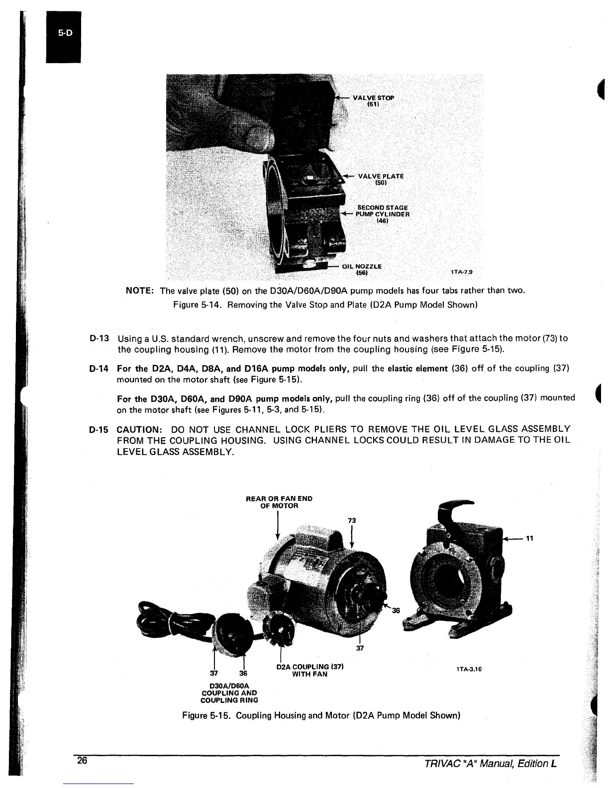
0-13
Using a U.S.
standard
wrench,
unscrew
and remove the
four
nuts
and washers
that
attach
the
motor
(73)
to
the
coupling
housing
(11).
Remove the
motor
from the
coupling
housing
(see Figure 5-15).
0-14
For the
D2A, D4A,
DBA, and
D16A
pump models
only,
pull the elastic element (36)
off
of
the coupling (37)
mounted on the
motor
shaft
(see
Figure 5-15).
For the
D30A, D60A, and
D90A
pump models only, pull the coupling ring (36)
off
of
the coupling (37) mounted
on
the
motor
shaft
(see
Figures 5-11, 5-3,
and
5-15).
0·15
CAUTION:
DO
NOT
USE
CHANNEL
LOCK PLIERS TO REMOVE THE
OIL
LEVEL
GLASS ASSEMBLY
FROM
THE
COUPLING HOUSING. USING CHANNEL LOCKS COULD RESULT IN DAMAGE TO THE
01
L
LEVEL
GLASS ASSEMBLY.
D30A/D60A
COUPLING
AND
COUPLING RING
lTA·3.16
Figure 5·15. Coupling Housing
and
Motor
(D2A
Pump Model Shown)
11
TRIVAC "A" Manual, Edition L
 Loading...


