Description
7
GA 01.600/10.02 - 07/01
By opening the gas ballast valve (2/1, optional) it is pos-
sible to admit a controlled quantity of air (gas ballast) into
the pump chamber while the compression process is in
progress. The gas ballast will prevent the condensation
of vapours within the pump up to the extent of the vapour
tolerance levels as stated in the specifications for the
pump (these data refer to water vapour).
A special lubrication system with forced lubrication of the
sliding bearings has been developed to enable operation
of the pump at intake pressures up to 1000 mbar.
An oil pump supplies the oil from the oil reservoir into a
high pressure oil system which in turn supplies all bea-
rings. From here the oil enters the pump chamber of the
vacuum pump.
The oil pump is located in bearing piece of the high vacu-
um stage. Separation of oil and gas in the pump involves
two stages. First an internal demister which is arranged
ahead of the exhaust valve ensures the creation of larger
droplets.
Next these are returned back to the oil reservoir via a
separation panel. This ensures a minimal loss of oil.
This and the combination with the large usable oil reser-
voir, results in long intervals between the oil exchanges,
even at high intake pressures.
The gas ballast valve (GB) is opened or closed by tur-
ning it (positions 0, 1, 2, 3).
Available as an option is a gas ballast valve having a
knurled screw (see Fig. 13 on page 28). When fully
opening this valve, the resulting gas flow will correspond
to that of valve position 3 in the following Table.
GB position Explanation
0 no gas ballast
maximum ultimate pressure
1 for cleaning the pump’s oil at a good ulti-
mate pressure and low oil consumption
2 good water vapour tolerance -
without producing excessive noise
3 maximum water vapour tolerance in
accordance with the technical data on
page 6.
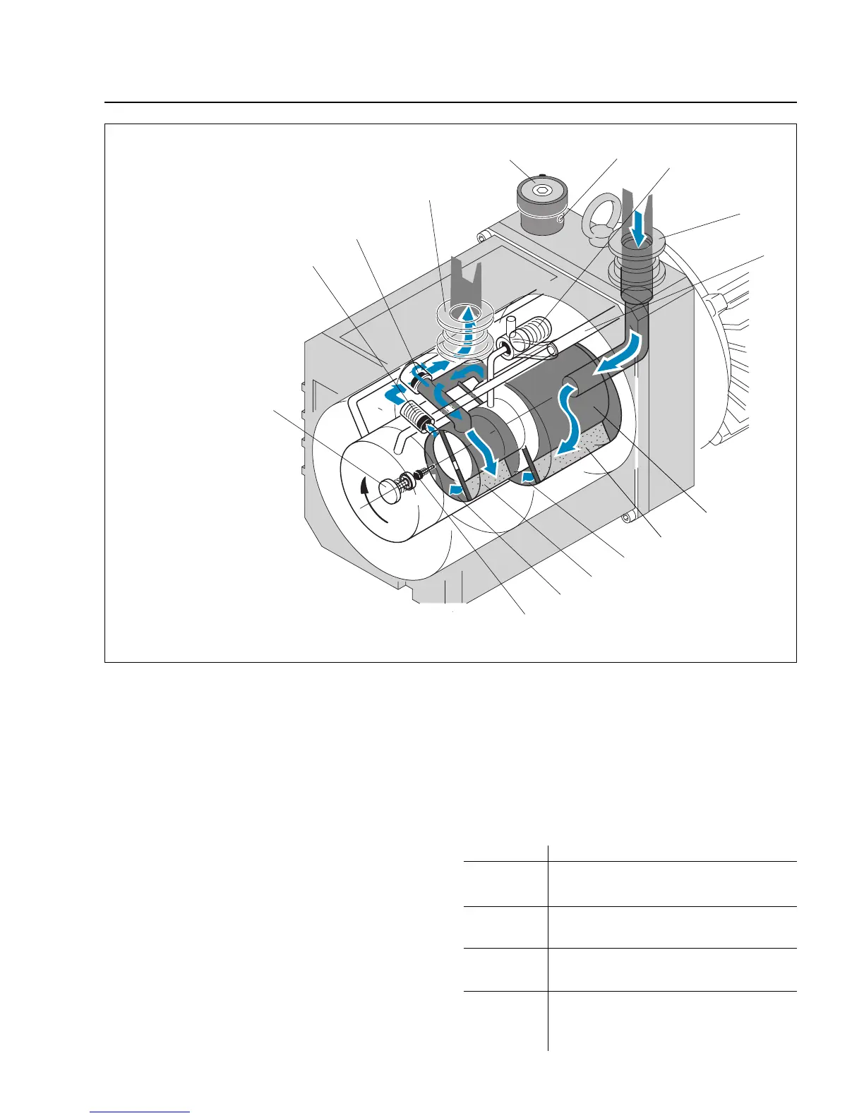
Key to Fig. 2
1 Gas ballast valve
2 Gas ballast inlet
3 Tandem valve
(vacuum protection)
4 Intake port
5 Oil feed (oil pump)
6 Rotor
7 Vane (HV)
8 High vacuum stage
(pump chamber)
9 Vane (FV)
10 Forevacuum stage
(pump chamber)
11 Non-return valve
12 Diaphragm valve
13 Exhaust valve
14 Bypass valve
15 Exhaust port
Fig. 2 Sectional view through a TRIVAC D 5 E pump
(other TRIVAC E models are similar)