- 39 -
3. The Indoor Unit Installation
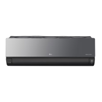
(1) Room Type Indoor Unit
The mounting wall should be strong and solid enough
to protect it from the vibration.
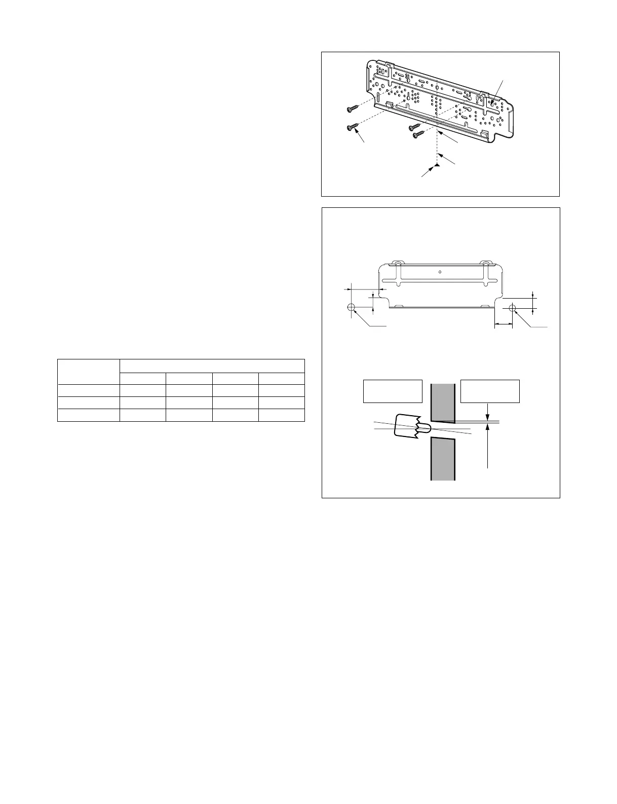
1. Mount the installation plate on the wall with four
Type "A" screws.
(If mounting the unit on the concrete wall, consider
using anchor bolts.)
• Always mount the Installation plate horizontally by
aligning the marking-off line by means of the
thread and a level.
2. Drill the piping hole with 70mm dia. holecore
drill.
• Line according to the arrows marked on lower the
left and the rght side of the Installation Plate.
The meeting point of the extended line is the cen-
ter of the hole.
• Drill the piping hole at either the right or the left and
the hole should be slightly slant to the outdoor
side.



 To Next Page