95
Electrical System Installation
Due to our policy of continuous product innovation, some specifications may change without notification.
©LG Electronics U.S.A., Inc., Englewood Cliffs, NJ. All rights reserved. “LG” is a registered trademark of LG Corp.
Table 16: Field-Installed Wiring / Cable Connections.
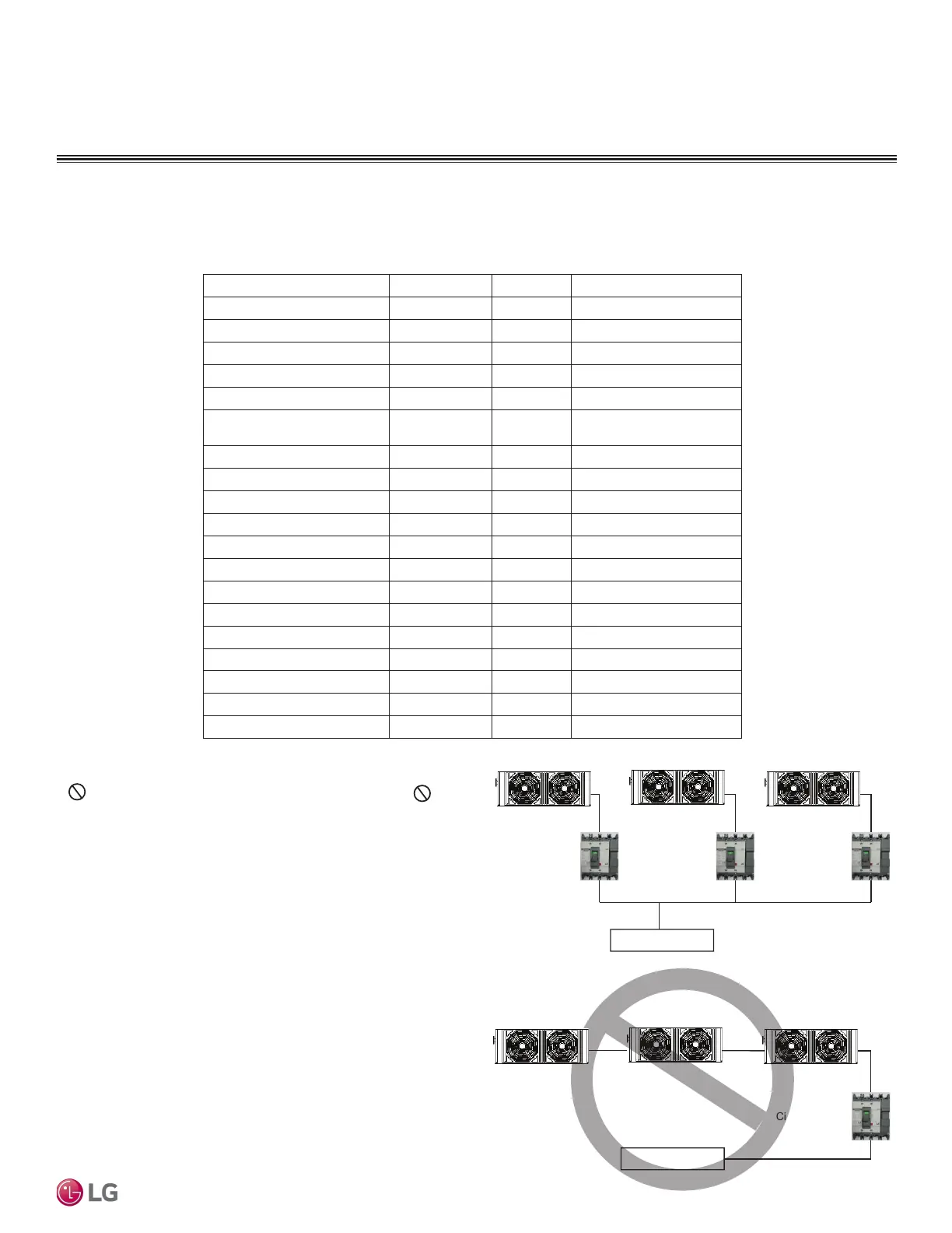
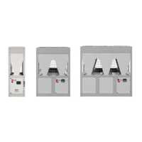
Table 15: Power Wiring System to Multiple, Grouped Chillers.
Circuit Breaker Circuit Breaker Circuit Breaker
Main Power Supply
Circuit Breaker
Main Power Supply
Refer to the wiring diagram for field-installed wiring. Only the main panel (HMI installed panel) requires wiring at the site. The control box is
shipped fully wired from the factory.
5. Circuit Breaker and Power Wiring Connections.
• Each chiller must have its own circuit breaker and direct power
wiring.
• Do not install one circuit breaker for multiple chillers. Do
not daisy chain the power wiring from the main power supply to
multiple chillers.
• Always label each circuit breaker and its connected chiller.
• Refer to the specification and electrical data when selecting circuit
breaker capacities. Follow all state, local, and NEC guidelines
when choosing and installing circuit breakers and power wiring.
ELECTRICAL
Wiring / Cable Installation
Index Signal type Location Remarks
Power DC Power 12 V DC Necessary
Central control communication Communication CH2 A, B Necessary
HMI communication Communication CH3 A, B Necessary
Modbus Communication CH4 A, B Optional (Field connection)
Ambient thermistor DI UI1, G Necessary
Flow switch DI UI5, G
Necessary
(Except H/P model)
Pump interlock DI UI6, G Optional (Field connection)
Remote On/Off DI DI1, GND Optional (Field connection)
Remote CO/HP DI DI2, GND Optional (Field connection)
Remote alarm DI DI3, GND Optional (Field connection)
Alarm status DO DO1, COM Optional (Field connection)
On/Off status DO DO2 Optional (Field connection)
Pump output DO DO3 Optional (Field connection)
Heater output DO DO5 Optional (Field connection)
Water spray output DO DO6 Optional (Field connection)
Global water inlet sensor AI UI3, GND Optional (Field connection)
Global water outlet sensor AI UI4, GND Optional (Field connection)
Remote Target Temp AI UI7, GND Optional (Field connection)
Remote Demand Limit AI UI8, GND Optional (Field connection)