Due to our policy of continuous product innovation, some specications may change without notication.
©LG Electronics U.S.A., Inc., Englewood Cliffs, NJ. All rights reserved. “LG” is a registered trademark of LG Corp.
(USE COPPER WIRE ONLY)
208-230/60/1
208/230V
R-134A Inverter
Compressor
RS 485
Communication Board
Crankcase
Heater
Inverter PCB
Cooling Fan
MAIN PCB
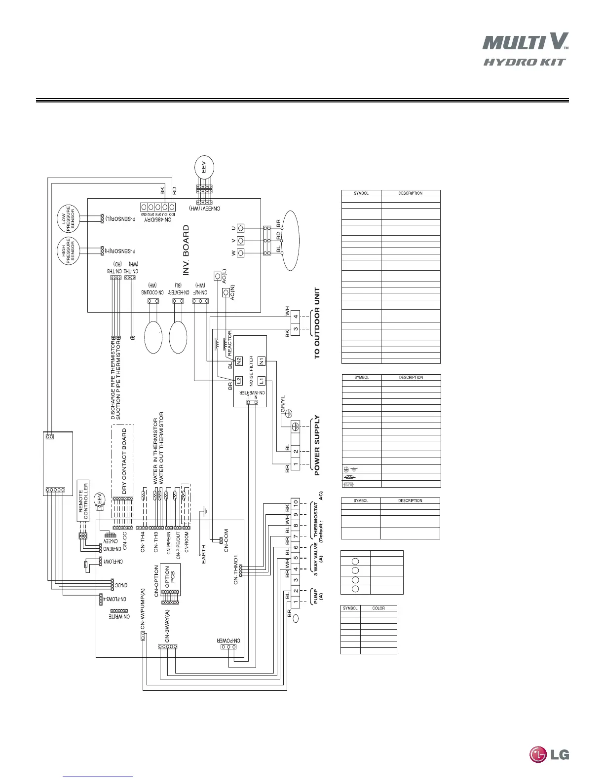
Field Connections - LG Sourced Accessories
Sockets and Connections - Main PCB
CN-3WAY (A)
CN-CC
CN-COM
CN-CC
CN-COM
CN-EEV
CN-FLOW1
To terminal strip A, screws 4,5,6
Optional LG Dry Contact connection
Multi V communication to outdoor or water
source unit
Optional LG Dry Contact connection
Multi V communication to outdoor or water
source unit
R410A EEV value
Factory mounted ow switch
CN-FLOW3-4
Power to RS-484 communications PCB
CN-OPTION
Option card interface
CN-PIPEIN
Heat exchanger - refrigerant pipe in
temperature
CN-PIPEOUT
Heat exchanger - refrigerant pipe out
temperature
CN-POWER
AC power to PCB
CN-REMO
Hydro Kit unit controller
CN-ROOM
LG Remote Temperature Sensor (optional)
CN-TH3(TOP/LEFT)
Heat exchanger-inlet water temperature
sensor
CN-TH3(BOTTOM/
CENTER)
Heat exchanger-outlet water temperature
sensor
CN-TH4(TOP)
Not used
CN-TH4(BOTTOM)
Hot water storage tank sensor (eld
mounted)
CN-THM01
To terminal strip A, screws 7,8,9,10
CN-WRITE
EARTH
Earth Ground
CN-DC
Communications link with inverter board
TERMINAL STRIP SCREW TERMINALS
A
A
A
A
1, 2
3
4,5,6
7,8, 9, 10
Field Supplied Connections
Wire Color Legend
BK
Black
BL
Blue
BrownBR
GR Green
RD Red
YL
Yellow
WH White
Not used
Sockets and Connections - Inverter and Other PCB’s
CN-COOLING
CN-Heater1
CN-N/F
AC (N)
AC (L)
W, U, V
CN-EEV1
Inverter PCB cooling fan
R134A compressor crankcase heater
Filtered power to inverter
Line power neutral
Line power 208-230/60/1
Inverter compressor connection
R134A circuit EEV
CN-485/DRY
Communications link
P-SENSOR (L)
Power to noise lter
P-SENSOR (H)
R134A high pressure sensor
CN-TH3
R134A compressor discharge pipe
thermistor
CN-TH2
R134A compressor suction pipe thermistor
CN-INVERTER
R134A low pressure sensor
Ground
Thermistor
Fuse
CN-ROOM
CN-REMO
CN-CC
CN-TH4 (BOTTOM)
LG remote temperature sensor (optional)
Remote mounted Hydro Kit Unit Controller
LG Dry Contact PCB interface (3rd party
binary signal enable/disable
Temperature sensor: Hot water storage tank
sensor (eld mounted)
A



 To Next Page