37
Installation
Due to our policy of continuous product innovation, some specifications may change without notification.
©LG Electronics U.S.A., Inc., Englewood Cliffs, NJ. All rights reserved. “LG Life’s Good” is a registered trademark of LG Corp.
ROUGHING-IN
Communications Cables
The minimum distance required between power wires and the communi-
cations cable is voltage/amperage dependent and in cases where either
are relatively high, the minimum distance may be more than two (2) inch-
es. Refer to the respective LG Multi V Outdoor Unit Engineering Manual
on www.lg-vrf.com for detailed information.
• Keep communications cables away from line voltage wiring, lighting
ballasts, and other devices emitting EMF energy.
• Maintain a minimum of two inches between line voltage wires and
communications or zone controller cables.
• Never use wire caps.
• Never splice communication cables.
• Star and Wye communications cable congurations are not acceptable.
• Never connect the Hydro Kit controller or other central control prod-
ucts such as AC Smart, PDI, or the LG building management system
gateway products to the communications cable between the indoor
unit and outdoor unit.
Procedure
1. Terminate all Multi V communications cables within the confines
of the Hydro Kit unit cabinet.
2. When pulling cable between components, leave enough slack
to properly route the cable through the unit keeping it away from
the line voltage wiring.
LG device communications cable voltage does not exceed 5 volts. LG
does not require a handy box to mount the Hydro Kit Unit Controller or
the optional LG Remote Wall Mounted Sensor. Check local code and
install per regulation.
3. Field provides a minimum of 18-2 AWG, stranded and shielded
communications wiring between the indoor units, heat recovery
boxes (if applicable), Hydro Kit, and outdoor units.
4. Ground the shield of the communications cable at the OUTDOOR
UNIT END ONLY.
Communications Cables Between the Water Source or Outdoor Unit and the Hydro Kit/Indoor Units/Heat Recovery Units
(Heat Recovery Systems Only)
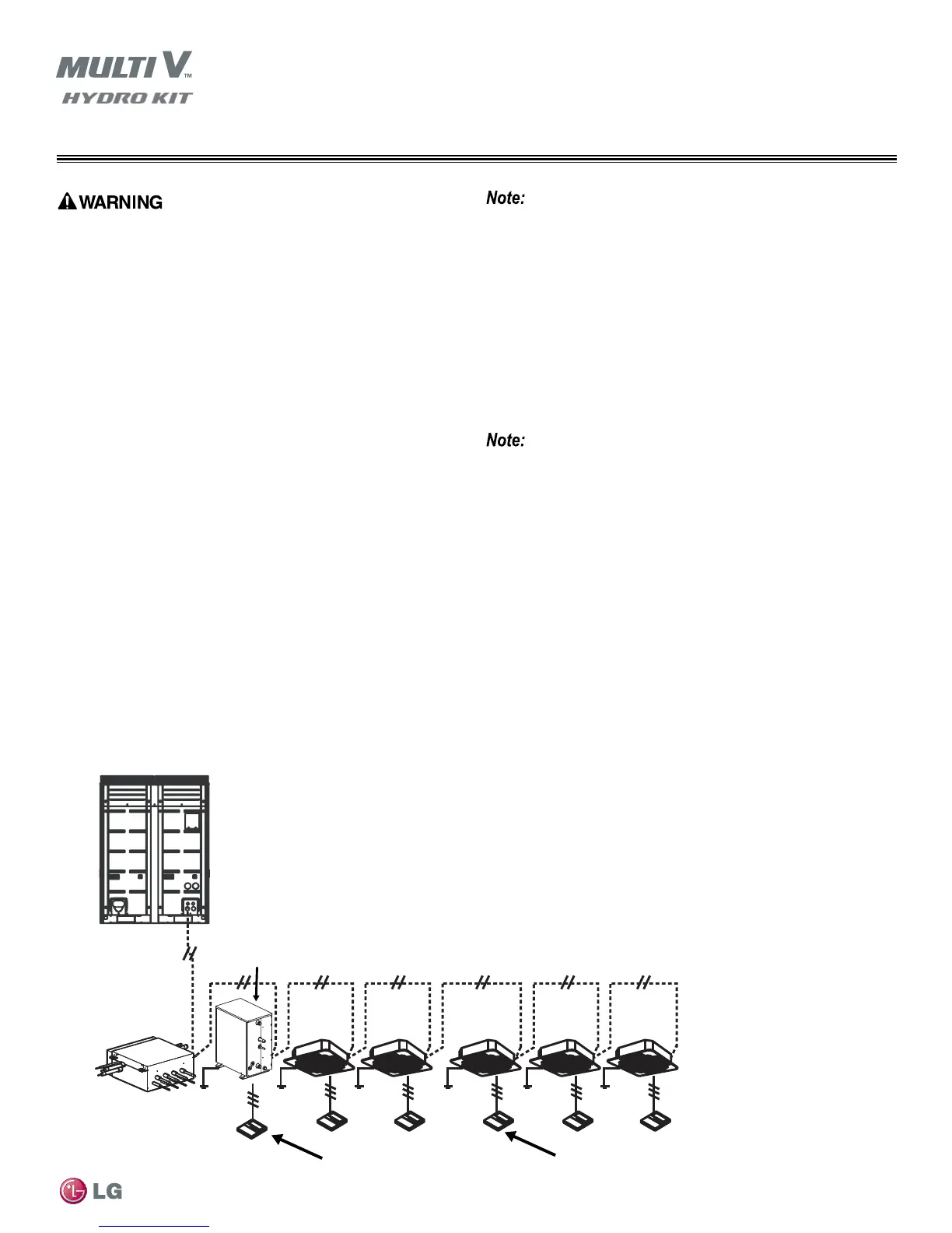
Refer to the applicable Outdoor or Water Source Unit manuals for cable routing and connection architecture. Figure 29 shows the correct
connection communication cable schematic, including the Hydro Kit among the indoor units. Note Figure 30, which shows improperly termi-
nated communication cable connections in a “starburst” pattern.
Master Outdoor Unit
IDU IDU IDU
IDU
IDU
Hydro Kit Unit Controller
Indoor Unit Zone Controllers
Heat Recovery Unit
for Heat Recovery
Systems Only
Hydro Kit
K2 or K3
Figure 29: Outdoor Unit Communications Labeling Schematic



 To Next Page