38
MULTI V Hydro Kit Installation Manual
Due to our policy of continuous product innovation, some specifications may change without notification.
©LG Electronics U.S.A., Inc., Englewood Cliffs, NJ. All rights reserved. “LG Life’s Good” is a registered trademark of LG Corp.
ROUGHING-IN
Communications Cables
Guidelines and Recommendations
•Use a 18-2 AWG, shielded, stranded cable between the outdoor unit(s) and the indoor
units / heat recovery units (Heat Recovery Systems Only).
•Cable must be rated for continuous exposure to temperature of up to 140°F.
•Maximum allowable length = 984 feet
•Firmly attach the cable; provide slack but secure in a way to prevent external forces from
being imparted on the terminal block.
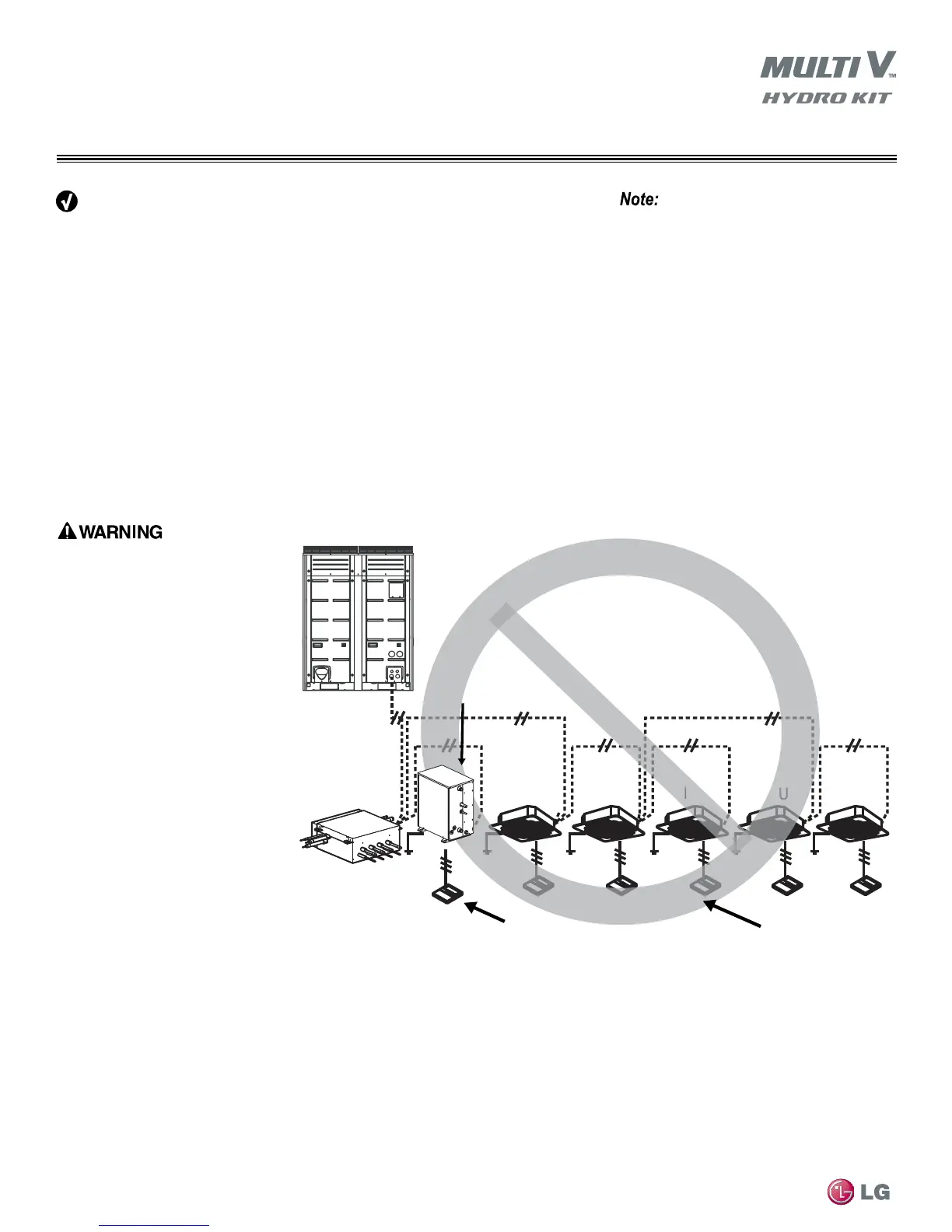
•Communications cable connecting the outdoor unit and Hydro Kit and other Multi V indoor
unit(s) should be installed and terminated in a daisy chain (BUS) configuration starting at
the outdoor unit as shown in Figure 29.
•Terminate the cable shield to a grounded surface at the outdoor unit(s) only. Cable shields
between connected devices shall be tied together and continuous from the outdoor unit(s)
to the last device connected.
Master Outdoor Unit
IDU IDU IDU
IDU
IDU
Hydro Kit Unit Controller
Heat Recovery Unit
for Heat Recovery
Systems Only
K2 or K3
Hydro Kit
Indoor Unit Zone Controllers
Figure 30: ImproperlyTerminatedCommunicationsCable—MultipleCoreCableinaStarburstConguration
Select eld supplied cable insulation material
based on NEC and local code requirements.
• Ring and spade terminals used to con-
nect communications cables MUST be
copper bearing. Do NOT use ter-
minals that are galvanized or nickle
plate over steel.
• Always verify the communication cable
is connected to a communications
terminal on the outdoor unit(s). Never
apply line voltage power to the com-
munication cable connection. If contact
is made, the PCBs may be damaged.
• The shield of the communications
cable connecting the outdoor unit(s)
to the Hydro Kit(s) and other indoor
units should be grounded only to the
outdoor unit(s) frame(s). Tie the shield
of each cable segment together using
a wire nut at the Hydro Kit(s) and other
indoor units.
• Never ground the shield of the commu-
nications cable to the Hydro Kit indoor
unit frame, or other grounded entities
of the building.
• Never use a common multiple-core
communications cable. Each communications bus shall be provided a separate cable (i.e., between outdoor unit(s) and indoor
units; outdoor units and central controller(s)). If communications cables of separate systems are wired using a common multiple-
core cable, it will result in a poor communications signal and unacceptable system operation.
• Position the power wiring a minimum of two (2) inches away from the communication cables to avoid operation problems caused
by electrical interference. Do not run both in the same conduit.



 To Next Page