74
MULTI V Hydro Kit Installation Manual
Due to our policy of continuous product innovation, some specifications may change without notification.
©LG Electronics U.S.A., Inc., Englewood Cliffs, NJ. All rights reserved. “LG Life’s Good” is a registered trademark of LG Corp.
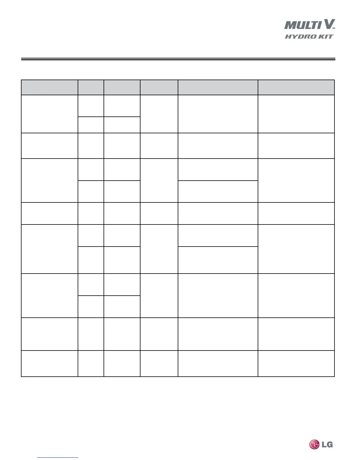
Table 26: Third Party Accessories (sold separately)
Accessory
Hydro Kit
Model
Connection
Voltage
Options
Description Use
Hydro Kit Circuit Water
Pump Interlock
1
K3 TB-1,2
208-230/60/1
Hydro Kit water circuit circulating
pump interlock (use a field
provided pilot relay).
Provides pump ON/OFF control
based on Hydro Kit control
logic.
K2 TB-11,12
Solar Heating Circuit
Water Pump
Interlock
1,2,3
K2 TB-4,5 208-230/60/1
Solar heating circuit circulating pump
interlock (use a field provided
pilot relay).
Provides pump ON/OFF control
based on Hydro Kit control
logic.
208-230/60/1
Conventional
Thermostat
1,4
K3 TB-7,8,9,10
208-230/60/1
Single stage heating only.
Monitors and/or controls (optional)
the Hydro Kit based on the
conditioned space temperature.
K2
TB-17,18,19,20
& Harness Plug
C to A
Single stage heating/cooling manual
changeover.
24 VAC
Conventional
Thermostat
4
K2
TB-17,18,19,20
& Harness Plug
C to B
24 VAC
Single stage heat/cool, must be
manual changeover model.
Monitors and/or controls (optional)
the Hydro Kit based on the
conditioned space temperature.
Mechanical Thermostat
1
K3 TB-7,8,9,10
---
Single stage manual changeover.
Monitors and/or controls (optional)
the Hydro Kit based on the
conditioned space temperature.
K2
TB-17,18,19,20
& Harness Plug
C to A
Single stage heating only.
Hydro Kit Circuit 3-Way
Domestic Water Divert-
ing Valve
1
K3 TB-4,5,6
208-230/60/1
Valve A 208-230/60/1
3-wire SPDT
Diverting valve - circulates water to/
from the comfort conditioning
equipment and the Hydro Kit
water storage tank.
K2 TB-8,9,10
Hydro Kit Circuit 2-Way
In-oor Heating
Isolation Valve
1
K2 TB-14,15,16 208-230/60/1
Valve (A) 208-230/60/1
2 -wire NO or NC
Partial circuit water isolation valve
prevents condensate from
forming on floors containing
in-floor heating pipe while
operating in the cooling mode.
Solar Heating System-
Interface Kit
1
K2 TB-1,2,3 208-230/60/1
Valve (B)208-230/60/1
3-wire SPDT
Diverting valve circulates water
to/from the Ancillary (Solar)
Heating Interface and the
Hydro Kit heating circuit.
Hydro Kit Accessories
TB = Terminal Block NO = Normally Open
NC = Normally Closed SPDT = Single Pole Double Throw
1
Maximum combined current draw of all connected accessories must be equal to or less than 5 Amp
@ 208-230/60/1.
2
Must have contacts rated for 208-230/60/1
3
1” FPT both ends
4
Must have contacts rated for 24VAC
All communication cable to be minimum 18 AWG, 2-conductor, stranded, shielded, and must comply
with applicable local and national codes.
Power wiring cable is field provided and must comply with the applicable local and national codes.
 Loading...