ART COOL
TM
| 25
Art Cool
TM
Mirror
'XHWRRXUSROLF\RIFRQWLQXRXVSURGXFWLQQRYDWLRQVRPHVSHFL¿FDWLRQVPD\FKDQJHZLWKRXWQRWL¿FDWLRQ
©
/*(OHFWURQLFV86$,QF(QJOHZRRG&OLIIV1-$OOULJKWVUHVHUYHG³/*´LVDUHJLVWHUHGWUDGHPDUNRI/*&RUS
Electrical Wiring Diagram
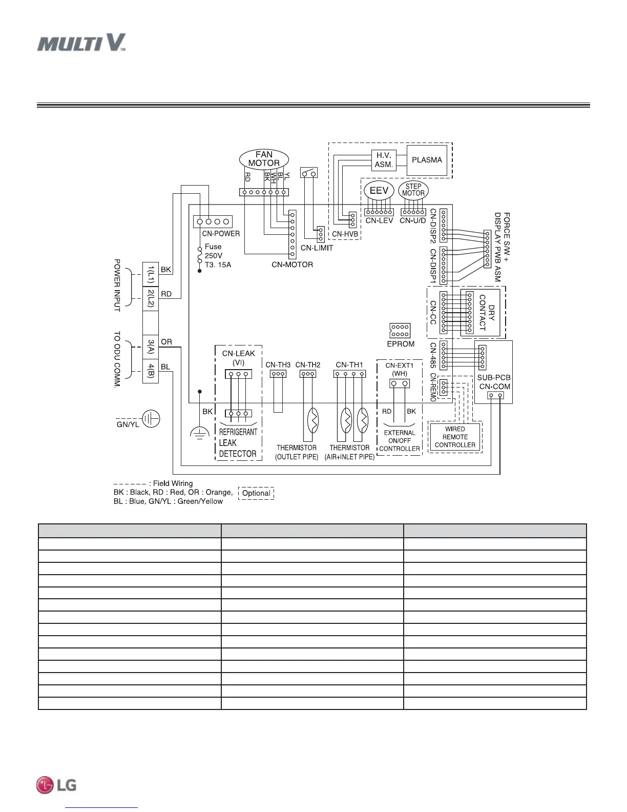
6%DQG6&)UDPHV
Figure 12: ARNU053~153SBR4 and ARNU183-243SCR4 Wiring Diagram.
ART COOL
TM
MIRROR
PCB Connection Purpose Function
CN-POWER AC Power supply AC Power line input for indoor controller
CN-MOTOR Fan motor output Motor output of BLDC
CN-HVB* Air cleaner* Air cleaner control*
CN-LEV EEV output EEV control output
CN-U/D Step motor Step motor output
CN-DISP2 Display Display of indoor status
CN-DISP1 Display Display of indoor status
CN-CC Dry contact Dry contact line
CN-485 Communication Connection between indoor and outdoor units
CN-REMO Remote controller Remote control line
CN-EXT1 External ON / OFF controller External ON / OFF controller connection
CN-TH1 Return air and inlet pipe thermistor Return air and inlet pipe thermistor connection
CN-TH2 Outlet pipe thermistor Outlet pipe thermistor connection
CN-TH3 Float switch Float switch connection
Table 12: SB and SC Frame Wiring Diagram Legend.
)LOWHUDFFHVVRULHVDUHDYDLODEOHVHSDUDWHO\$OZD\VIROORZDOOORFDOVWDWHDQGQDWLRQDOEXLOGLQJFRGHVZLWKWKHXVHRIWKLVRUDQ\SURGXFW
7RHQDEOH*HQHUDWLRQIHDWXUHVRXWGRRUXQLW',3VZLWFKQRPXVWEHVHWWR213OHDVHUHIHUWRWKH0XOWL9,90XOWL9:DWHU,90XOWL96
(QJLQHHULQJ0DQXDOIRUDGGLWLRQDOLQIRUPDWLRQ
 Loading...