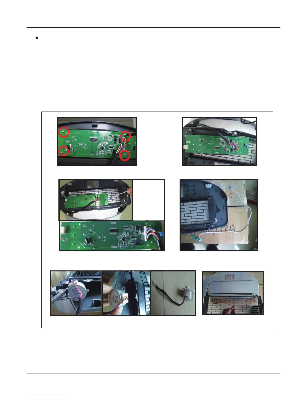
Fig 2-1 Fig 2-2
Fig 2-3 Fig 2-4
Fig 2-5 Fig 2-6 Fig 2-7
Fig 2
2-1 Screw the 4 screws fixing the display PCB. (Fig 2-1)
2-2 Remove the display PCB from display panel. (Fig 2-2)
2-3 Remove the 2 intermials of singal receiver and swing fan motor. (Fig 2-3)
2-4 Remove the singal receiver. (Fig 2-4)
2-5 Remove the 2 screw fixing the swing fan motor. (Fig 2-5)
2-6 Remove the swing fan motor. (Fig 2-6)
2-7 remove the inlet and swing leaf. (Fig 2-7)
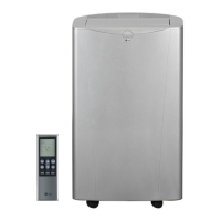
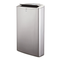
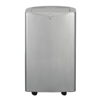
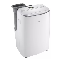
2 Top panel components (Fig 2)

 Loading...