-98-
11. Compressor Troubleshooting
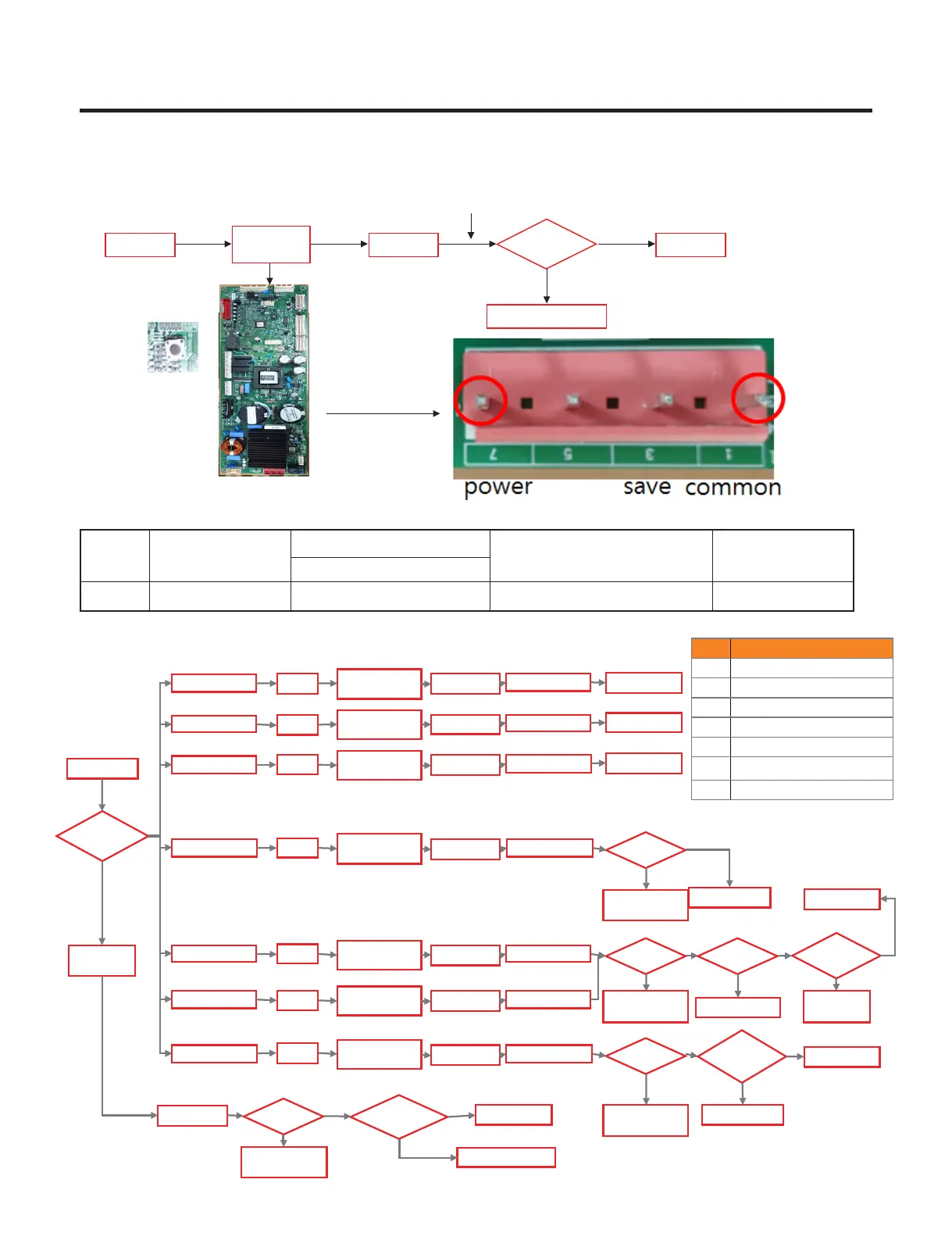
PCB Check (Simplify)
Test Mode
Power Off Power On PCB OK
Replace Driver PCB
N
Y
Time>30sec
& V≒200
Con201
Disconnect
A-inverter
TEST 1 Mode
Protection Logic
Check Voltage about 200V
past 30second after turn on
Check Comp .
Y
N
PCBA Output
> 60V?
N
Check
Cycle leakage
N
Y
Y
LED7 Blinks
LED2 Blinks
LED1 Blinks
Replace PCB
Comp.
Action?
Replace PCB
Y
LED6 Blinks
Comp.
Action?
LED Blinking?
Comp.
Action?
PCBA Output
> 60V
Replace PCB
N
N
Y
N
Not Cooling
Harness
wiring?
Y
Repair H arness
N
Y
LED8 Blinks
Replace PCB
Reset
LED7 Blinks
LED1 Blinks
LED2 Blinks
LED6 Blinks
LED8 Blinks
LED3 Blinks LED3 Blinks
LED5 Blinks
Comp.
Action?
LED5 Blinks
Check
Comp.
Check Comp .
Check the Comp.
Test Mode
1 In put
About 5min
Check
Cycle leakage
Cycle
Cycle leakage
Check
Cycle leakage
About 5min
About 5min
About 5min
About 5min
About 5min
About 5min
About 5min
Reset
Reset
Reset
Reset
Reset
Reset
Test Mode
1 In put
Test Mode
1 In put
Test Mode
1 In put
Test Mode
1 In put
Test Mode
1 In put
Test Mode
1 In put
Test Mode
1 In put
PCBA Output
> 60V
Replace PCB
Replace PCB
Y
N
Y
N
LEDTrip Information
1Current/Voltage SensingError
2Over Stroke
3Comp Connection Error
5 Comp Lock Error
6Over CurrentError
7IPM Error
8Communication Error
Ref.
Comp
FLD165NBMA
Refer
TEST1 Forced Starting TDC (Full Stroke)
Display & sound
Display ON, Buzz 1 time
- Simple Check Flow Chart
Copyright © 2019 LG Electronics Inc.
All rights
reserved. Only training and service purposes.
 Loading...