Chapter 7. MK PROGRAMMING
7 - 2
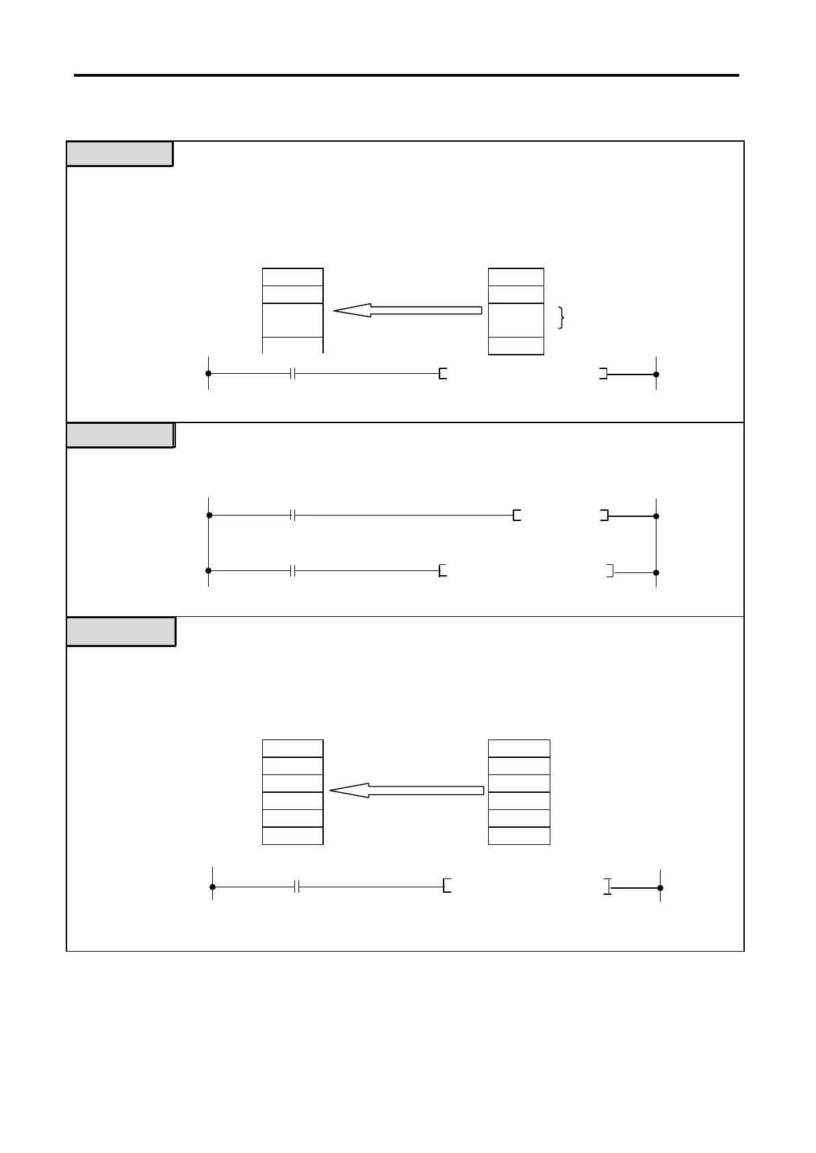
Example 1
When the high speed counter module is mounted on the first expansion base and the data at address 5 of
the
Buffer Memory is read to the two words D15 and D16.
Example 2
When the same data as the example 1 is read but a pulse relay is used.
Example 3
When the high speed counter module is mounted on the slot 4 of the main base and the 6-word data
from address 6 of the Buffer Memory are read to the D1 to D6.
[Fig 7.3] 16-Bit Data Read Example
CPU
High Speed Counter Module
Buffer Memory
Register (address)
Read
D15 (Data)
(Data) 5 Current count value of
CH0
D16 (Data) (Data) 6
CPU High Speed Counter Module
D1 Data 1 Data 1 10
D2 Data 2 GET Data 2 11
D3 Data 3 Data 3 12
D4 Data 4 Data 4 13
D5 Data 5 Read Data 5 14 Data of CH1
D6 Data 6 Data 6 15
 Loading...