Table 340:Outdoor Unit Piping Connections.
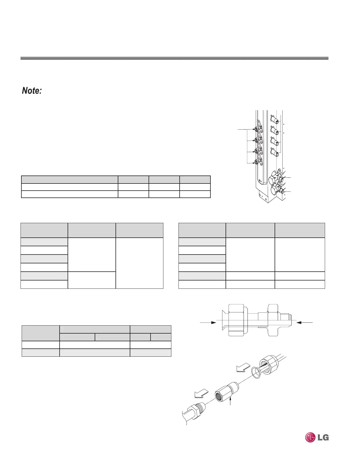
Figure 72:Multi F Refrigerant Pipe Connections
(LMU36CHV shown as example).
Avoid Pipe Damage
• When routing field-provided piping, avoid damaging the outdoor unit from
excessive vibration.
• Correctly route the piping so it does not make contact with mounting bolts.
Allow room for field installation.
• Properly insulate the liquid and gas lines separately up to the point of con-
nection at the unit frame.
• See table below for Multi F outdoor unit connection types.
Main gas
valve
Main liquid
valve
Gas Piping Connections
Liquid
Piping
Connections
A-UNIT
B-UNIT
C-UNIT
D-UNIT
Connection sockets (included as a factory-supplied accessory with
the indoor units) may need to be used when piping the indoor units
to the outdoor unit.
Indoor Unit
Capacity
Vapor (in., OD) Liquid (in., OD)
A B A B
18,000 Btu/h Ø3/8 → Ø1/2, Ø1/2 → Ø5/8 Ø1/4 → Ø5/8
24,000 Btu/h Ø3/8 → Ø1/2 N/A
A
B
Flare
to
Indoor
Unit
Flare
to
Outdoor
Unit
1. Align the center of the piping sections and tighten the flare nut by
hand.
2. Tighten the flare nut with a torque wrench, using the arrows on
the wrench as a guide, until a click is heard.
INSTALLATION & LAYOUT BEST PRACTICES
Refrigerant Piping System Layout
Multi F Outdoor Unit to Indoor Unit Piping Connections
Outdoor Unit Piping Connections LMU18CHV LMU24CHV LMU36CHV
Liquid Line Connection (in., OD) x Qty. 1/4 x 2 1/4 x 3 1/4 x 4
Vapor Line Connection (in., OD) x Qty. 3/8 x 2 3/8 x 3 3/8 x 4
Table 341:Indoor Unit Pipe Sizes.
Table 342:Connection Socket Dimensions.
Figure 73:Connection Socket Diagram.
Using the Connection Socket
Connection Socket
(Factory-supplied with
the indoor unit)
Figure 74:Performing Connections.
Indoor Unit Capacity
Vapor Line
Connection (in., OD)
Liquid Line
Connection (in., OD)
7,000 Btu/h
Ø3/8
Ø1/4
9,000 Btu/h
12,000 Btu/h
15,000 Btu/h
18,000 Btu/h
Ø1/2
24,000 Btu/h
Table 343:Indoor Unit Piping Connections.
Indoor Unit Capacity
Vapor Line
Connection (in., OD)
Liquid Line
Connection (in., OD)
7,000 Btu/h
Ø3/8 Ø1/4
9,000 Btu/h
12,000 Btu/h
15,000 Btu/h
18,000 Btu/h Ø5/8 Ø3/8
24,000 Btu/h Ø1/2 Ø1/4
Due to our policy of continuous product innovation, some specications may change without notication.
©LG Electronics U.S.A., Inc., Englewood Cliffs, NJ. All rights reserved. “LG” is a registered trademark of LG Corp.
372 | DESIGN & PRACTICES
Multi F and Multi F MAX Indoor Unit Engineering Manual

 Loading...