INSTALLATION & LAYOUT BEST PRACTICES
Refrigerant Piping System Layout
Multi F MAX Outdoor Unit System Piping Connections
Branch Distribution to Indoor Unit Piping Connections
• Install indoor unit liquid and vapor refrigerant pipes (and connection wiring) to the appropriate branch distribution ports.
• Clearly note on the indoor unit’s refrigerant piping (liquid, vapor) which branch distribution port it is connected to (A, B, C, D).
Outdoor Unit Piping Connections LMU540HV
Liquid Line Connection (in., OD) x Qty. 3/8 x 1
Vapor Line Connection (in., OD) x Qty. 3/4 x 1
Avoid Pipe Damage
• When routing field-provided piping, avoid damaging the outdoor unit from excessive vibration.
• Correctly route the piping so it does not make contact with mounting bolts. Allow room for field installation.
• Properly insulate the liquid and gas lines separately up to the point of connection at the unit frame.
• See table below for Multi F MAX outdoor unit connection types.
Table 344:Outdoor Unit Piping Connections.
Table 345:Branch Distribution Unit Piping Connections.
Table 346:Indoor Unit Piping Connections.
Branch Distribution Unit PMBD3620 PMBD3630 PMBD3640 PMBD3641
Piping Connections to Outdoor Unit
Liquid (in., OD) x Qty. Ø3/8 x 1
Vapor (in., OD) x Qty. Ø3/4 x 1
Piping Connections to Indoor Units
Liquid (in., OD) x Qty. Ø1/4 x 2 Ø1/4 x 3 Ø1/4 x 4 Ø1/4 x 3, Ø3/8 x 1
Vapor (in., OD) x Qty. Ø3/8 x 2 Ø3/8 x 3 Ø3/8 x 4 Ø3/8 x 3, Ø5/8 x 1
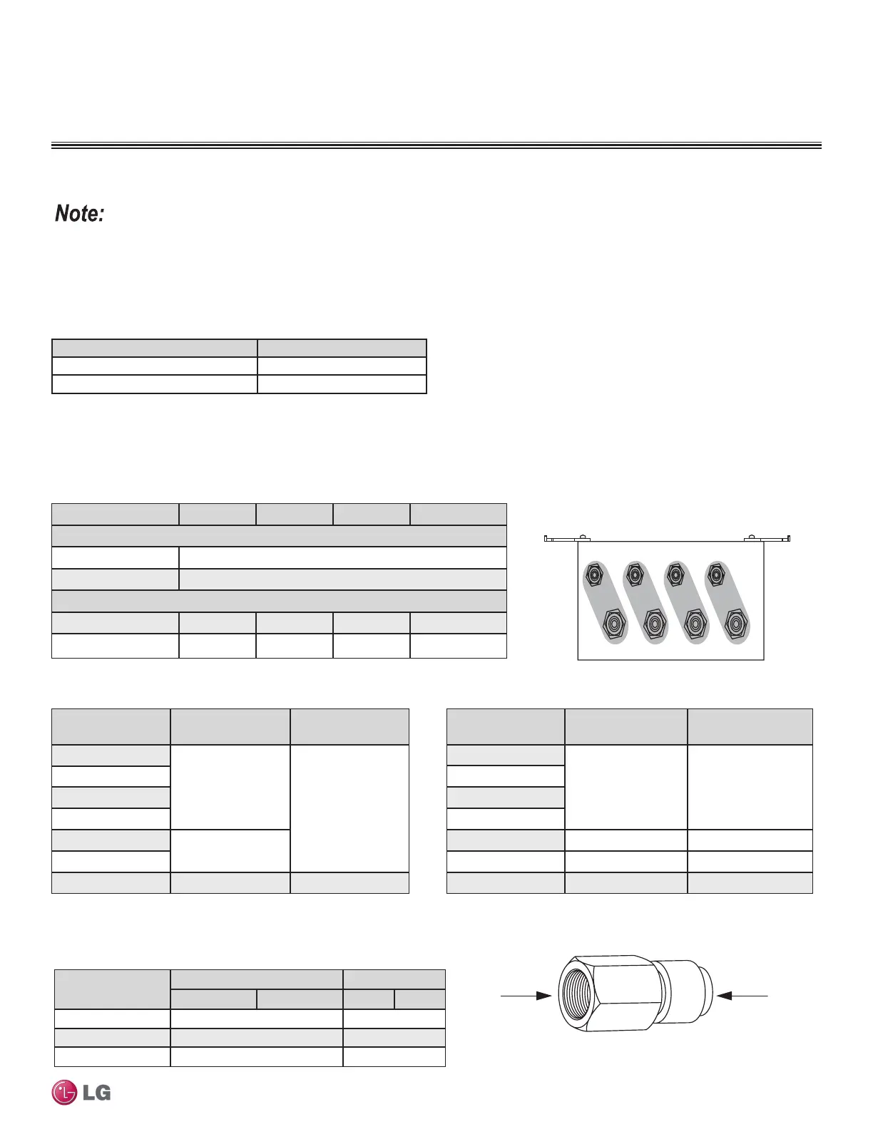
Table 347:Connection Socket Dimensions.
Connection sockets (included as a factory-supplied accessory with the indoor units) may need to be used when piping the indoor units to the
branch distribution unit.
Indoor Unit Capacity
Vapor (in., OD) Liquid (in., OD)
A B A B
18,000 Btu/h Ø3/8 → Ø1/2, Ø1/2 → Ø5/8 Ø1/4 → Ø3/8
24,000 Btu/h Ø3/8 → Ø1/2 N/A
36,000 Btu/h Ø1/2 → Ø5/8 Ø1/4 → Ø3/8
Figure 75:Branch Distribution Ports to Indoor Units.
Figure 76:Connection Socket Diagram.
Indoor Unit Capacity
Vapor Line
Connection (in., OD)
Liquid Line
Connection (in., OD)
7,000 Btu/h
Ø3/8
Ø1/4
9,000 Btu/h
12,000 Btu/h
15,000 Btu/h
18,000 Btu/h
Ø1/2
24,000 Btu/h
36,000 Btu/h Ø5/8 Ø3/8
Indoor Unit Capacity
Vapor Line
Connection (in., OD)
Liquid Line
Connection (in., OD)
7,000 Btu/h
Ø3/8 Ø1/4
9,000 Btu/h
12,000 Btu/h
15,000 Btu/h
18,000 Btu/h Ø5/8 Ø3/8
24,000 Btu/h Ø1/2 Ø1/4
36,000 Btu/h Ø5/8 Ø3/8
Table 348:Indoor Unit Pipe Sizes.
Due to our policy of continuous product innovation, some specications may change without notication.
©LG Electronics U.S.A., Inc., Englewood Cliffs, NJ. All rights reserved. “LG” is a registered trademark of LG Corp.
DESIGN & PRACTICES | 373
Refrigerant Piping Design and Best Practices
 Loading...