35
Installation Manual
Due to our policy of continuous product innovation, some specifications may change without notification.
©LG Electronics U.S.A., Inc., Englewood Cliffs, NJ. All rights reserved. “LG” is a registered trademark of LG Corp.
INSTALLATION
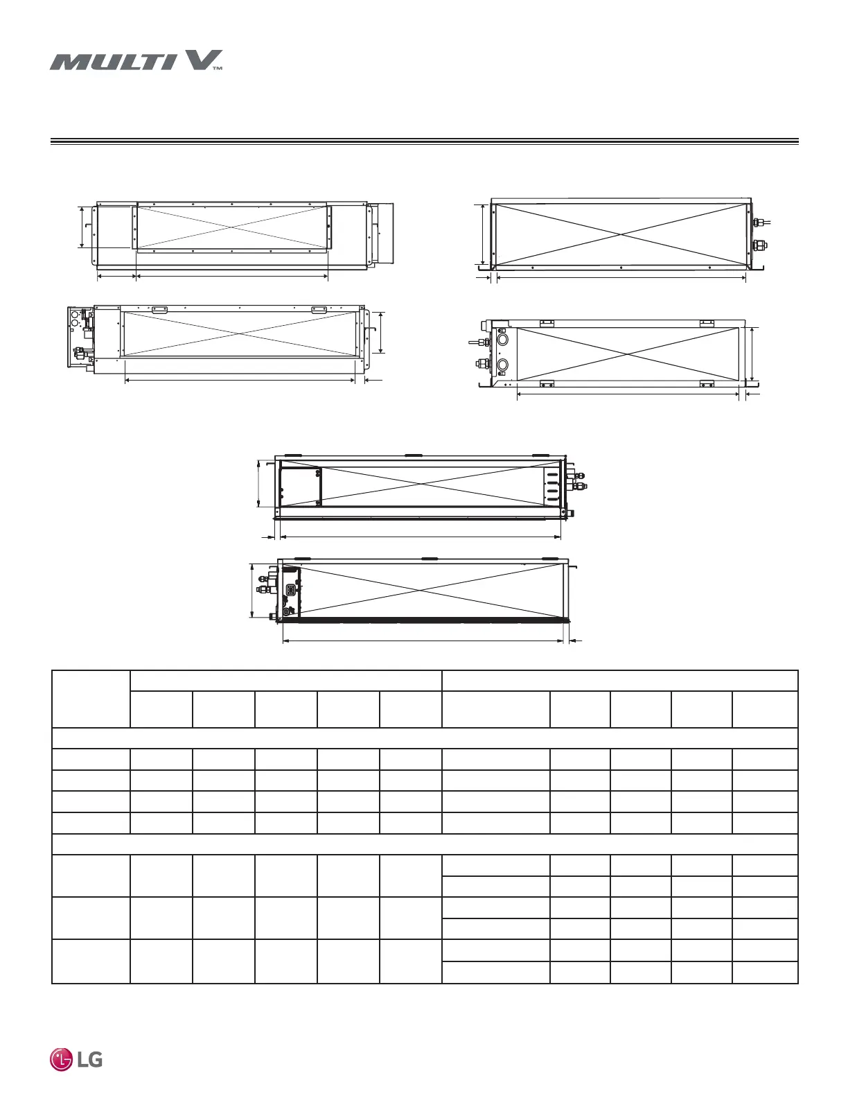
Duct Connection Dimensions
Chassis
Code
Supply Duct Connection Return Duct Connection
Type L1 L2 L3
Flange
Depth
Opening Location L5 L6 L7
Flange
Depth
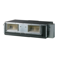
High-Static Ducted Indoor Units
M1 Flange 6-21/32 33-23/32 1-13/32 3/4 Rear 9-1/16 33-7/16 15/16 No Flange
M2 Flange 7-7/8 47-15/32 1-13/32 27/32 Rear 9-3/32 47-1/2 15/16 No Flange
M3 Flange 11-7/16 47-19/32 1-21/32 13/16 Rear 12-21/32 47-9/16 7/8 No Flange
B8 Flange 12-7/16 44-1/4 6-3/4 1 Rear 15-7/16 55 2 1-1/8
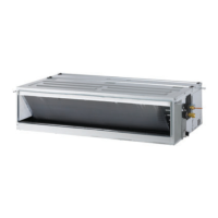
Low-Static Ducted Indoor Units
L1 Flange 5-7/8 26 13/16 5/8
Rear 6-1/8 26 3/4 No Flange
Bottom 6-1/16 26 3/4 No Flange
L2 Flange 5-7/8 33-13/16 13/16 5/8
Rear 6-1/8 33-11/16 3/4 No Flange
Bottom 6-1/16 33-13/16 3/4 No Flange
L3 Flange 5-7/8 41-3/4 13/16 5/8
Rear 6-1/8 41-11/16 3/4 No Flange
Bottom 6-1/16 41-11/16 3/4 No Flange
Table 14: Duct Connection Dimensions (in.).
Figure 12: High-Static Ducted (B8) Indoor Unit Duct
Connection Dimensions.
Figure 13: Low-Static Ducted (L1/L2/L3) Indoor Unit Duct
Connection Dimensions.
L3
L1
L2
L5
L7
L6
L2
L3
L6
L5
Supply
Return
Supply
Return
Figure 14: High-Static Ducted (M1/M2/M3) Indoor Unit Duct
Connection Dimensions.
L2
Return
Supply
L1
L6
L5
L3
L7
 Loading...