36
Multi V Ducted Indoor Units
Due to our policy of continuous product innovation, some specifications may change without notification.
©LG Electronics U.S.A., Inc., Englewood Cliffs, NJ. All rights reserved. “LG” is a registered trademark of LG Corp.
GENERAL INSTALLATION GUIDELINES
Maintenance Clearances
Chassis Code
Control Panel Access Major Maintenance Access
Location C1 C2 C3 Location A1 A2 A3*
High-Static Ducted Indoor Units
M1 Right End 8 8 10 Bottom 40 32 12
M2 Right End 8 8 10 Bottom 50 28 12
M3 Right End 8 8 12 Bottom 50 28 15
B8 Right End 12 14 18 Bottom 62 28 19
Low-Static Ducted Indoor Units
L1 Right End 10 12 8 Bottom 30 25 8
L2 Right End 10 12 8 Bottom 38 25 8
L3 Right End 10 12 8 Bottom 46 25 8
Table 15: Minimum Maintenance Clearances (in.).
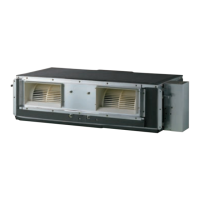
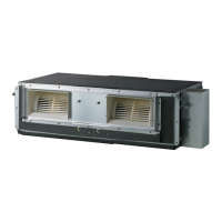
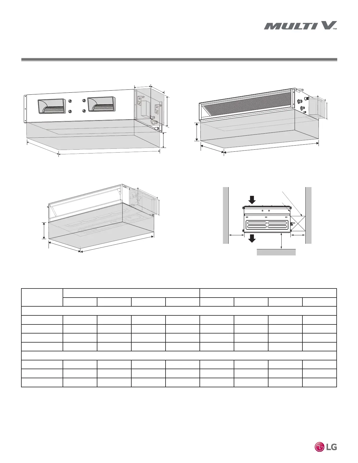
Figure 15: High-Static Ducted (B8) Indoor Unit
Maintenance Clearances.
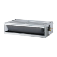
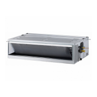
Figure 16: Low-Static Ducted (L1/L2/L3) Indoor Unit
Maintenance Clearances.
Figure 17: High-Static Ducted (M1/M2/M3) Indoor Unit
Maintenance Clearances.
*Does not apply when the ceiling surface below can be removed.
A1
A2
A3
C2
C1
C3
A1
A3
C2
C1
C3
Figure 18: High-Static Ducted (B8/M1/M2/M3) Indoor Unit
Maintenance Clearances.
[Unit: inch]
Top view
Front
Inspection hole
23-5/8 x 23-5/8
Control box
39-3/8
Air outlet
vents
Air inlet vents
23-5/8
10
 Loading...