38
Multi V Ducted Indoor Units
Due to our policy of continuous product innovation, some specifications may change without notification.
©LG Electronics U.S.A., Inc., Englewood Cliffs, NJ. All rights reserved. “LG” is a registered trademark of LG Corp.
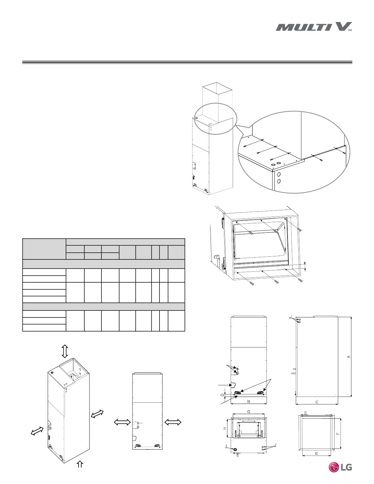
Duct Work For Vertical / Horizontal Air Handler Units
• Use at least ten (10) M4-25L screws when attaching the supply
duct to the vertical-horizontal air handler unit.
• To prevent vibration transmission, install exible connectors be-
tween the supply duct and the vertical-horizontal air handler unit.
If an electrical heater is included, the exible connector must be
constructed from a heat-resistant material.
• When routed through unconditioned spaces, ducts must be
insulated and covered with vapor barriers.
• Internal acoustical insulation lining may be necessary for a metal
duct system if it does not have a 90° elbow and ten (10) feet of
main duct to the rst branch takeoff.
• Fibrous ducts could be used as a substitute if built and installed
in accordance with the most recent edition of the Sheet Metal
and Air Conditioning Contractors’ National Association (SMAC-
NA) Construction Standard.
• Fibrous ducts and acoustical linings must follow National Fire
Protection Association (NFPA) Standards 90A or 90B as tested
by UL Standard 181 for Class 1 ducts.
• Seal around the ducts to prevent air leaks.
At least ten (10) screws
(M4-25L)
At least six (6) screws (M-4-25L)
More than
1 inch
Figure 21: Attaching Ducts to the Vertical / Horizontal Air Handler Unit.
Top
Front
Bottom
Right Side
Refrigerant Pipe
Connections
Drain Connections
for Horizontal-Left
Installation
Drain
Connections
for Upflow
Installation
Air Filter Cover
Model No.
Dimensions (inches)
A B C
D E F G H
Height Width Depth
NJ Chassis
ARNU123NJA4
48-5/8 18 21-1/4 1-9/16 17-1/2 20 17 12-1/8
ARNU183NJA4
ARNU243NJA4
48-5/8 18 21-1/4 1-9/16 17-1/2 20 17 12-1/8
ARNU303NJA4
ARNU363NJA4
NK Chassis
ARNU423NKA4
48-5/8 25 21-1/4 1-9/16 24-1/2 20 24 12-1/8ARNU483NKA4
ARNU543NKA4
Figure 22: Vertical / Horizontal Air Handler Unit Duct Connection
Dimensions Diagram.
Table 17: VAHU Unit Duct Connection Dimensions Table.
General Mounting - Vertical / Horizontal Air Handler Units
GENERAL INSTALLATION GUIDELINES
More than
23-5/8 inches
0 inches*
Minimum 14 inches
0 inches*
*When using top panel access holes
for power wiring / communications cable
Rear
0 inches
Front
Minimum 14 inches
Figure 23: Clearances Requirements for Vertical / Horizontal Air Handler Units.
 Loading...