10 _ Ceiling Concealed Duct(High Static)
Indoor Units
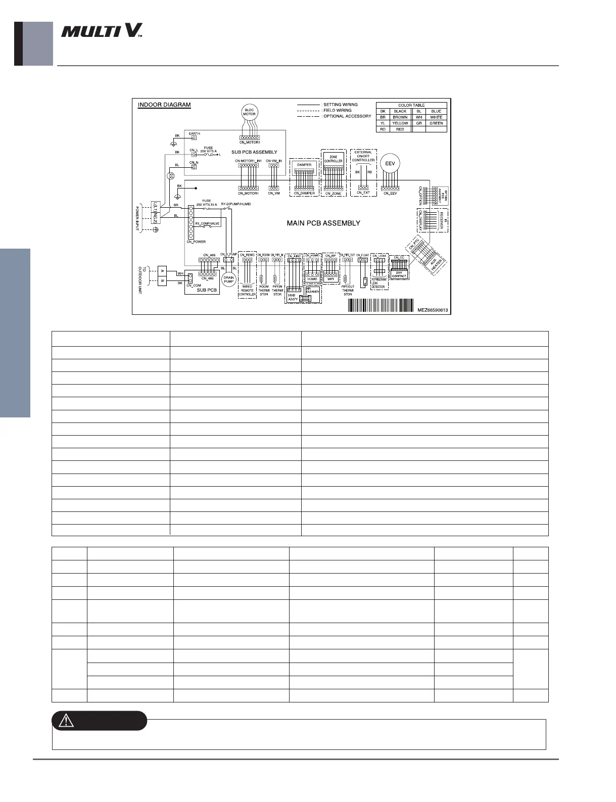
5. Wiring Diagrams
BG Chassis
CONNECTOR NUMBER
LOCATION POINT FUNCTION
CN-POWER AC Power supply AC Power line input for indoor controller
CN-MOTOR1 Fan motor output Motor output of BLDC
CN-MOTOR2 Fan motor output Motor output of BLDC
CN-D_PUMP Drain pump output AC output for drain pump
CN-COM Communication Connection between indoor and outdoor
CN-EEV EEV Output EEV Control output
CN-FLOAT Float switch input Float switch sensing
CN-PIPE_IN Suction pipe sensor Pipe in thermistor
CN-PIPE_OUT Discharge pipe sensor Pipe out thermistor
CN-ROOM Room sensor Room air thermistor
CN-REMO Remote controller Remote control line
CN-ZONE Zontroller Zone control line
CN-DISPLAY RF Remote controller RF Remote control line
CN-CC Dry contact Dry contact line
CN-EXT External On/Off External On/Off signal input
For Multi V Models, DIP switch 1, 2, 6, 8 must be set OFF.
Function Description Setting Off Setting On
Default
SW1
Communication
N/A (Default) - - Off
SW2
Cycle
N/A (Default) - - Off
SW3
Group Control
Selection of Master or Slave
Master Slave Off
SW4
Dry Contact Mode
Selection of Dry Contact Mode
Wired/Wireless remote controller selec-
tion of Manual or Auto operation Mode
Auto Off
SW5
Installation
Fan continuous operation
Continuous operation Removal - Off
SW6
Heater linkage
N/A - - Off
SW7
Ventilator linkage
Selection of Ventilator linkage
Linkage Removal Working
Off
Vane selection (Console)
Selection of up/down side Vane
Up side + Down side Vane
Up side Vane Only
Region selection
Selection tropical region General model Tropical model
SW8
Etc.
Spare - - Off
 Loading...