123
Installation
Due to our policy of continuous product innovation, some specications may change without notication.
©LG Electronics U.S.A., Inc., Englewood Cliffs, NJ. All rights reserved. “LG” is a registered trademark of LG Corp.
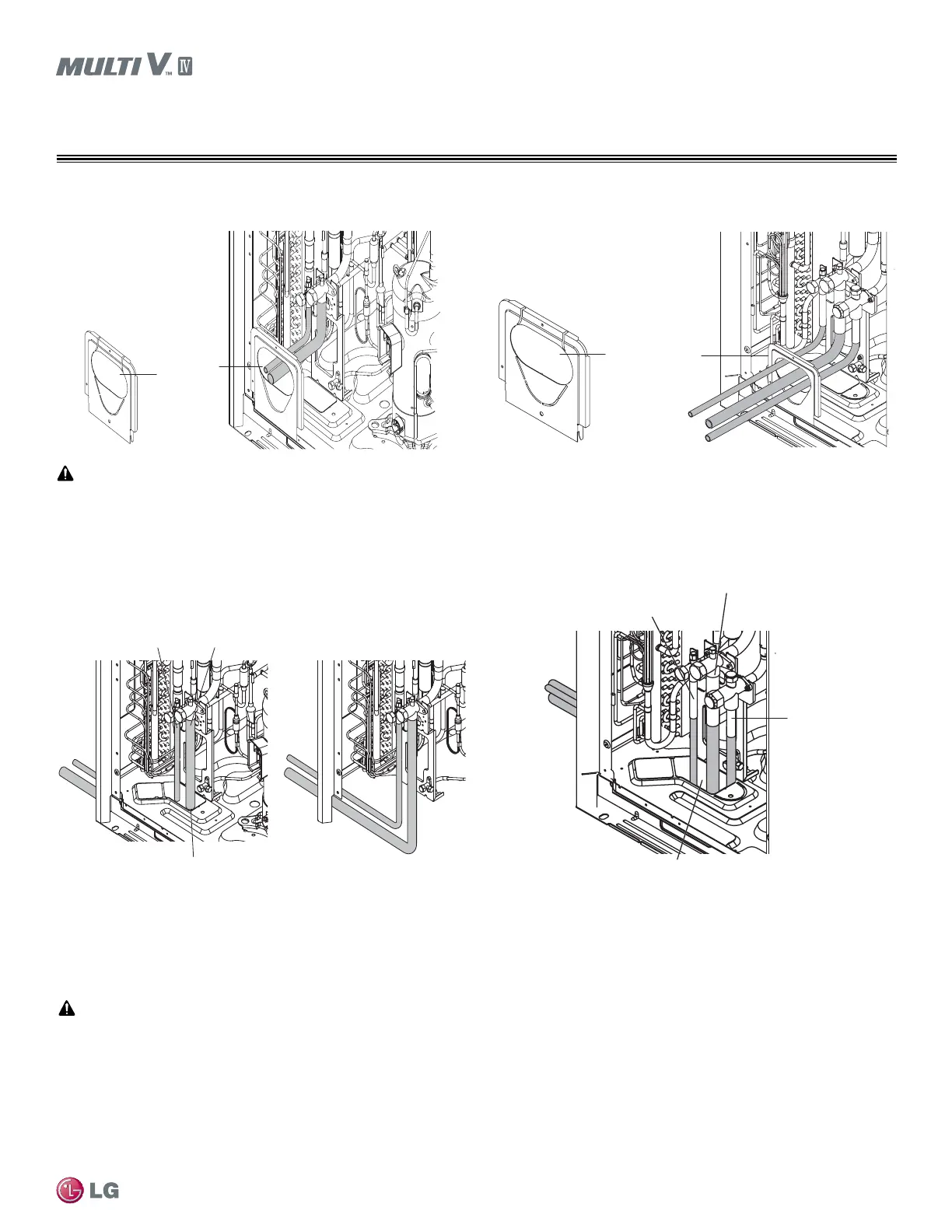
REFRIGERANT PIPING DESIGN
Remove only liquid/gas pipe Knock out
Figure 37: Refrigerant Piping Paths Using Access Hole at Bottom of
Heat Pump Outdoor Unit.
Liquid pipe
Low Pressure Gas pipe
High Pressure
Gas pipe
Remove pipe knock out
Figure 38: Refrigerant Piping Paths Using Access Hole at Bottom of
Heat Recovery Outdoor Unit.
Pipe Connections Between Outdoor Units and Indoor Units
Attaching the Compressor
Brackets are installed on the inverter compressor base to protect the unit during transportation.
The brackets must be removed or noise or vibration will occur during unit operation.
To remove compressor brackets:
1. Open the front panel.
2. Remove the brackets.
3. Attach the compressor to the outdoor unit frame with a nut and washer.
Pipe Knock Out for
Liquid/Gas pipes
Pipe Knock Out for
Liquid /Gas pipes
Figure 39: View of Heat Pump Refrigerant Piping Connections Using
the Front Access Hole.
• Do not damage the piping or the outdoor unit frame base when opening the access holes.
• Remove any burrs that were created when opening the access holes.
• Add a protective sleeve around the access hole to prevent the wires from being damaged during installation.
Figure 40: View of Heat Recovery Refrigerant Piping Connections
Using the Front Access Hole.
 Loading...

