92
MULTI V IV System Installation Manual
Due to our policy of continuous product innovation, some specications may change without notication.
©LG Electronics U.S.A., Inc., Englewood Cliffs, NJ. All rights reserved. “LG” is a registered trademark of LG Corp.
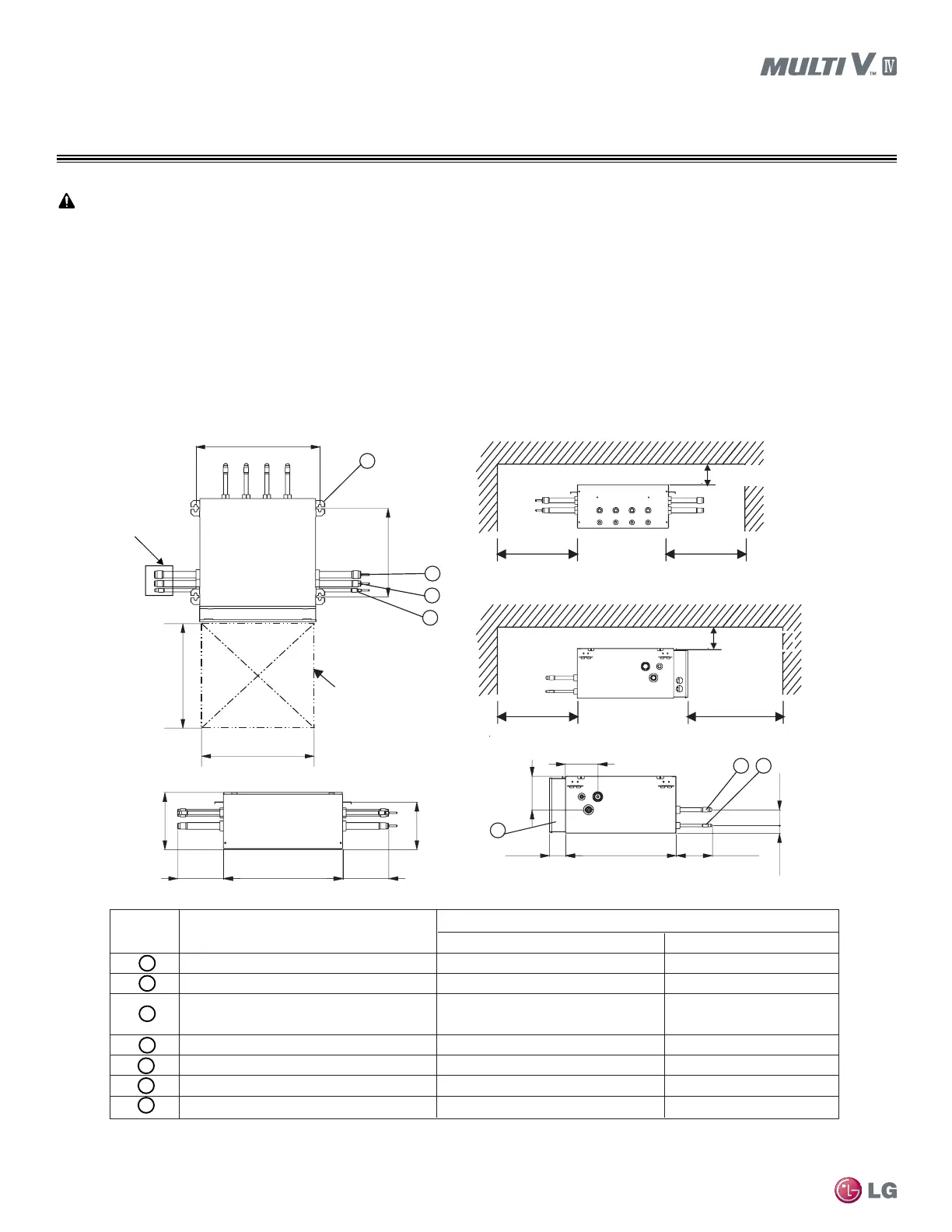
Mounting / Anchoring the Heat Recovery Unit
INSTALLATION
Heat recovery units are for use Heat Recovery systems only.
Select an installation space for the heat recovery unit that meets the following conditions:
• Install the heat recovery unit indoors.
• Ensure there is enough space in the installation area for service access.
• Refrigerant pipes must not exceed lengths specified by LG Electronics.
• Do not install the heat recovery unit in a location where it would be subjected to strong radiation heat from heat sources.
• Avoid an installation environment where oil splattering, vapor spray, or high-frequency electric noise could occur.
• Install the heat recovery unit in a location where any sound it may generate will not disturb occupants in the surrounding rooms.
• Install the refrigerant piping and electrical wiring system in an easily accessible location.
Inspection door
(servicing space)
18-15/16
13-5/8
11-13/16
more
11-13/16
more
11-13/16
more
17-3/4
more
(Servicing space) (Servicing space)
(Servicing space)
(Servicing space)
1
2
3
54
6
7
17-7/8
6-7/8
6-7/8
8-5/8
7-3/16
16-1/2
2-7/16
5-7/16
4-7/8
5-1/16
1-3/16
17-3/4
17-3/4
3-15/16 more
(Servicing space)
3-15/16 more
(Servicing space)
2-3/8
Description
PRHR031A / PRHR041APRHR021A
1 Low pressure vapor pipe connection port 1-1/8Ø
7/8
Ø
Brazed connection
2 High pressure vapor pipe connection port Brazed connection
7/8Ø3/4Ø Brazed connection
3 Liquid pipe connection port
5/8
Ø
Brazed connection (PRHR041A)
1/2
Ø
Brazed connection (PRHR031A)
4 Indoor unit vapor pipe connection port
5/8
Ø
Brazed connection
5/8
Ø
Brazed connection
5 Indoor unit liquid pipe connection port 3/8Ø Brazed connection
3/8
Ø
Brazed connection
6 Control box - -
7 Metal hanger tab 3/8 or 5/16 3/8 or 5/16
Part Name
No.
Unit: inch
Unit: inch
1
22
2
2
Brazed connection
3/8Ø Brazed connection
Cap the pipes at the end of
series-connected branches
of heat recovery units.
Figure 6: Heat Recovery Control Unit Minimum Space Requirements.
1
Locate the inspection door at the control box side of the heat recovery unit.
2
If reducers are used, space for service access must be increased to match the dimensions of the reducer. See dimensions on pages 81-83
for more information.
 Loading...

