91
Installation
Due to our policy of continuous product innovation, some specications may change without notication.
©LG Electronics U.S.A., Inc., Englewood Cliffs, NJ. All rights reserved. “LG” is a registered trademark of LG Corp.
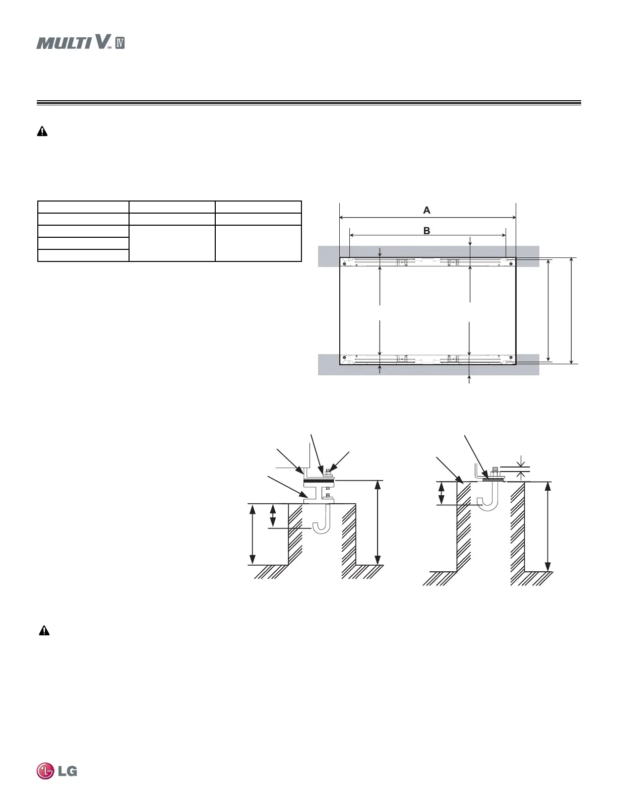
Figure 4: Close up of Anchor Bolts.
• Securely fasten all four (4) corners to the
supporting base.
• If not otherwise directed by the structural
engineer or local codes, Use a 7/8 inch or
1/2 inch diameter J-bolt. Use a hexagon nut
with a spring washer.
• Include anti-vibration material chosen by the
acoustics engineer.
• Include enough space for refrigerant piping
and electrical wiring when installing through
the bottom of the unit.
• Use an H-beam, concrete support, or other
acceptable support structure designed by a
structural engineer.
All referenced materials are to be eld-supplied as specied by the designer. Images are not to scale. Images are for reference only and are
not intended to be used for design purposes.
Note:
Mounting / Anchoring the Outdoor Unit
INSTALLATION
Unit: Inch
8
8
Nut
3
3
Spring Washer
Unit Mounting
Foot
Anti-vibration
Material
Four Bolts
Required
H-Beam
Concrete
Base
4
Three Threads
28-3/4
29-15/16
2-9/16
2-9/16
Unit: Inch
≥2-9/16≥2-9/16
Figure 5: Location of the Anchor Bolts.
Capacity (ton) A (inches) B (inches)
6 36-1/4 31-3/16
8
48-13/16 43-3/810
12
Table 23: Anchor Bolt Location Specications.
Job site conditions may require routing utilities—including the refrigerant piping, condensate pipe, and electrical wiring—under the unit base.
If job site conditions warrant, consider adding mounting rails under the unit. The unit may need to be elevated above the oor to provide the
necessary slope for proper condensate draining on long pipe installations.
 Loading...

