95
Installation
Due to our policy of continuous product innovation, some specications may change without notication.
©LG Electronics U.S.A., Inc., Englewood Cliffs, NJ. All rights reserved. “LG” is a registered trademark of LG Corp.
LATS MULTI V Piping Design
Software
The proper design and installation of the refrigerant piping system is a
critical element of the Multi V system. Multi IV Heat Pump requires two
pipes between system components – a liquid line and a vapor line. Multi
IV Heat Recovery requires three pipes between the outdoor unit and
the heat recovery unit – a liquid line, a low-pressure vapor line, and a
high-pressure vapor line. A properly designed refrigerant piping system
ensures that refrigerant is delivered to the evaporator coil’s electronic
expansion valve (EEV) in a pure liquid state free of gas bubbles. A
proper design also ensures a sufficient refrigerant gas flow rate in
the vapor line that eliminates the possibility of refrigeration oil from
collecting in the vapor lines.
Refrigerant Piping Quality Assurance
LG’s LATS Multi V software makes designing the refrigerant system easy. LATS Multi V is a Windows
®
-based application that assists the
engineer in the design of the refrigeration distribution pipe system, verifies the design complies with pipe design limitations, applies capac-
ity correction factors, and calculates the system refrigerant charge. The piping system can be entered manually into LATS from a one-line
pipe diagram. To ensure that the refrigerant piping design meets LG’s quality standards, a LATS refrigerant piping design must be
provided with every Multi V IV order. Following the installation, if any changes or variations to the design were necessary, a new
“as-built” LATS piping design software report must be created and provided to LG prior to system commissioning.
Systems that are close to the standard application limits may be converted into a conditional application by field changes to pipe equivalent
lengths. User should always check the LATS report actual pipe layout versus pipe limits. The user may want to increase pipe lengths when
design conditions are approaching the Standard Application Piping Rule limits to force the LATS program to engineer the system using the
“Conditional Application Pipe Rules,” which will increase the diameter of the main and a few branch segments to minimize the possibility of
required pipe changes due to field installation variations.
REFRIGERANT PIPING DESIGN
Computer-assisted Refrigerant Pipe Design
It is imperative the designer avoids creating excessive pressure drop. When liquid refrigerant is subjected to excessive pressure drop, liquid
refrigerant will change state and “ash” to vapor. Vapor present in a stream of liquid refrigerant before reaching the electronic expansion
valve (EEV) results in a loss of system control and causes damage to the valve. The pipe system must be designed in a manner that avoids
the creation of unwanted vapor.
Any eld changes, such as re-routing, shortening or lengthening a pipe segment, adding or eliminating elbows and/or ttings, re-
sizing, adding, or eliminating indoor units, changing the mounting height or moving the location of a device or tting during installa-
tion should be done with caution and ALWAYS VERIFIED in LATS MULTI V SOFTWARE BEFORE supplies are purchased or installed.
Doing so may lead to a more protable installation, reduce the potential for rework, and will reduce the potential for multiple visits
to the job site to complete the system commissioning.
Adjusting LATS Multi V Output for Altitude
When a system is installed at elevations significantly above sea level, the designer must also consider the impact air density has on the
capacity of the indoor and outdoor units. LATS does not de-rate indoor unit capacity for high altitude applications. Locally accepted altitude
correction factors must be applied to indoor unit capacities.
Creating a Balanced Piping System
Unlike designing duct-work or chilled and hot water pipe systems where balancing dampers, ball valves, orifices, circuit setters, or other flow
control devices can be installed to modify or balance the flow of cooling medium, these cannot be used in a VRF system. Therefore, vari-
able refrigerant flow systems have to be designed to be “self balanced.” Balanced liquid refrigerant distribution is solely dependent on the
designer choosing the correct pipe size for each segment. Pipe sizing considerations include pipe length, pipe segment pressure drop
relative to other pipe segments in the system, type and quantity of elbows, bends present, fitting installation orientation, and end use device
elevation differences.
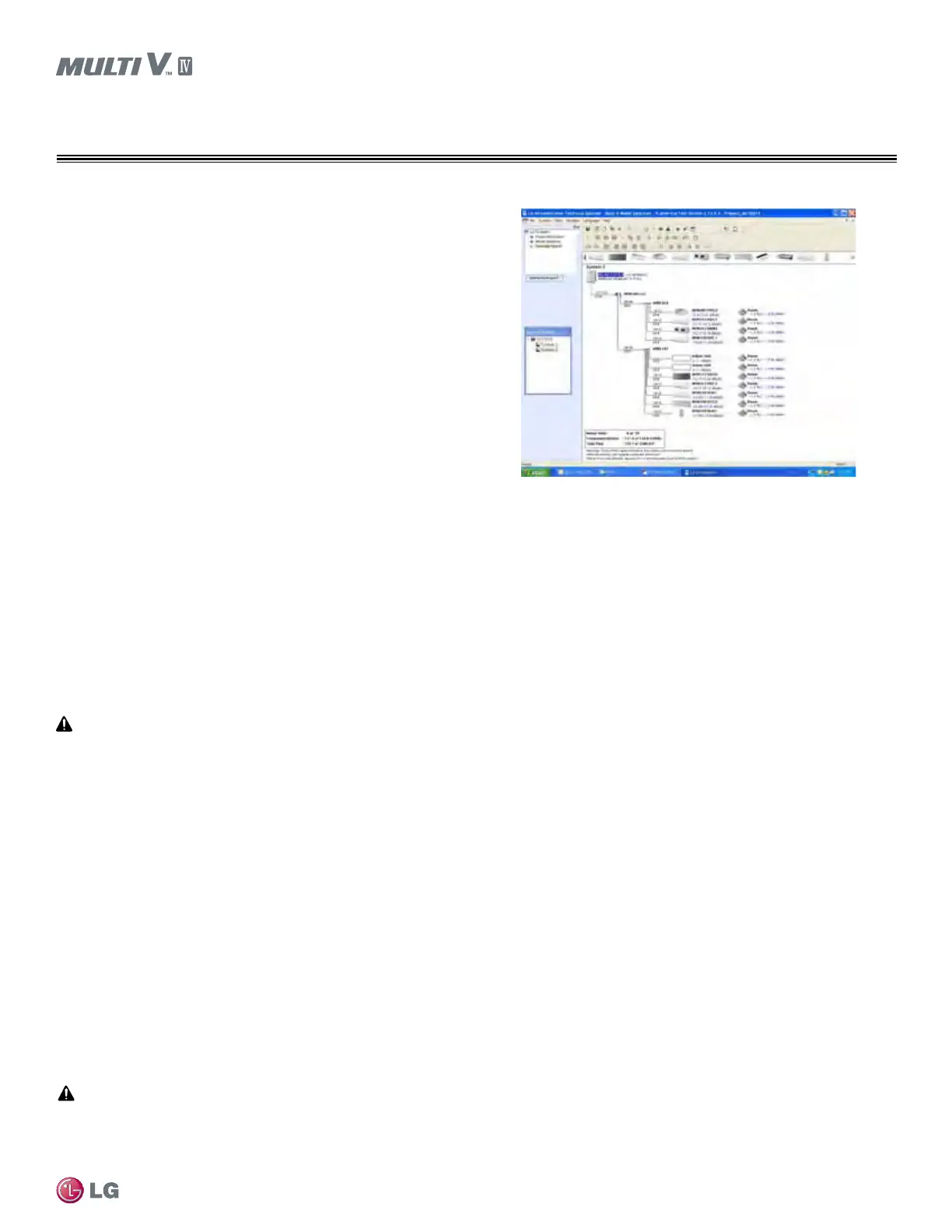
Figure 7: Screenshot of LATS Pipe System Design Tool in Tree Mode.
 Loading...

