130
MULTI V IV System Installation Manual
Due to our policy of continuous product innovation, some specications may change without notication.
©LG Electronics U.S.A., Inc., Englewood Cliffs, NJ. All rights reserved. “LG” is a registered trademark of LG Corp.
REFRIGERANT PIPING INSTALLATION
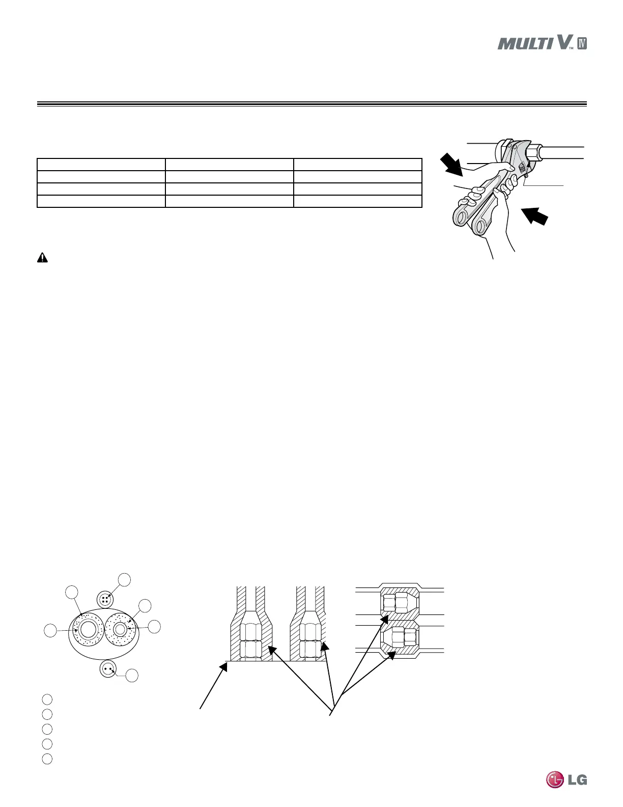
Refrigerant Pipe Connections
Union
Figure 44: Tightening the Flare Nuts.
Pipe size (Inches O.D.) Tightening torque (ft-lbs) Width of the are (A [inches])
3/8Ø 24.1 - 29.4 1/2
1/2Ø 36.5 - 44.5 5/8
5/8Ø 45.5 - 55.6 3/4
1. When connecting the flare nuts, coat the flare (inside and outside) with polyvinyl ether (PVE)
refrigeration oil only.
2. Initially hand tighten the flare nuts using three (3) or four (4) turns.
3. To finish tightening the flare nuts, use both a torque wrench and a backup wrench.
4. After all the piping has been connected and the caps have been tightened, check for refrigerant gas leaks.
Table 46: Tightening Torque for Flare Nuts.
Loosening the Flare Nuts
Always use two (2) wrenches to loosen the flare nuts.
Do not use polyolyester (POE) or any other type of mineral oil as a thread lubricant. These lubricants are not compatible with PVE oil used in
this system and create oil sludge leading to equipment damage and system malfunction.
Tightening the Flare Nuts
Liquid Pipe
Communication Cables
Gas Pipe
Power Wiring
Insulation
A
B
C
D
E
E
D
D
B
A
C
Surface of
Indoor Unit Casing
Field-Provided
Pipe Insulation
Figure 45: Typical Pipe Insulation,
Power Wire and Communications
Cable Arrangement.
Figure 46: Typical Insulation Butt-
Joint at Indoor Unit Casing.
Figure 47: Typical Refrigerant
Flare Fitting Insulation Detail.
Refrigerant Piping System Insulation
To prevent heat loss/heat gain through the refrigerant piping, all refrigerant piping including liquid lines and vapor lines must be insulated
separately. Insulation must be a minimum 1/2″ thick, and thickness may need to be increased based on ambient conditions and local codes.
All refrigerant piping including Y-branch and Header connections, field-provided isolation ball valves, service valves, and elbows must be
completely insulated using closed-cell pipe insulation. All insulation joints must be glued with no air gaps. Insulation material must fit snugly
against the refrigeration pipe with no air space between it and the pipe. Insulation passing through pipe hangers, inside conduit, and/or
sleeves must not be compressed. Protect insulation inside hangers and supports with a second layer. All pipe insulation exposed to direct
sunlight and deterioration-producing elements must be properly protected with a PVC-aluminum vapor barrier jacket, or alternatively placed
in a weather-resistant enclosure such as a pipe rack with a top cover. The design engineer should perform calculations to determine if the
factory-supplied insulation jackets have sufficient thickness to meet local codes and to avoid sweating at jobsite conditions. Maximum refrig-
erant pipe temperature is 227°F; minimum refrigerant pipe temperature is -4°F. Add additional insulation if necessary.
 Loading...

