22
MULTI V IV System Installation Manual
Due to our policy of continuous product innovation, some specifications may change without notification.
©LG Electronics U.S.A., Inc., Englewood Cliffs, NJ. All rights reserved. “LG” is a registered trademark of LG Corp.
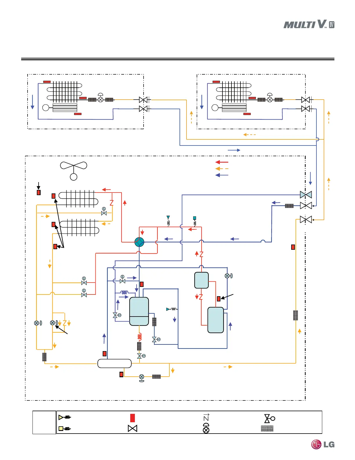
HEAT PUMP REFRIG. FLOW DIAGRAMS
Cooling Mode
ARUN072BTE4 / 072DTE4, ARUN096BTE4 / 096DTE4,
ARUN121BTE4 / 121DTE4
Accum
Inverter
Comp1
Oil
Separator
Receiver
Outdoor
Temperature
Sensor
Outdoor Unit
HEX Temperature
Sensor
Upper
Hot Gas Valve
Low
Hot Gas Valve
Low
Outdoor
EEV
Upper
Outdoor
EEV
Sub-cooling Circuit
Outlet Temperature
Sensor
Liquid Pipe
Temperature
Sensor
Comp
Discharge
Temperature
Sensor
Suction
Temperature
Sensor
Sub-cooling Circuit
Inlet Temperature
Sensor
Pressure
Switch
High Pressure
Sensor
4-Way Valve
Low
Pressure
Sensor
Oil Return
Receiver
Outlet
SC Suction
Comp
Vapor
Injection
Receiver
Inlet
Sub-cooling
Active Path
High Temperature High Pressure Gas
High Temperature High Pressure Liquid
Low Temperature Low Pressure Gas
Charging Port
Liquid Pipe
Gas Pipe
Sub-cooling HEX
Fan
S
S
S
S
S
S
S
M
Electronic
Expansion Valve
Fan
Indoor Heat Exchanger
M
Electronic
Expansion Valve
Fan
Indoor Heat Exchanger
M
ss
Check Valve
EEV
Solenoid Valve
SVC Valve
Pressure Sensor
Pressure Switch
Temperature Sensor
Remarks
Strainer
*8 ton and 10 ton units have 2 fans
 Loading...

