30
MULTI V IV System Installation Manual
Due to our policy of continuous product innovation, some specifications may change without notification.
©LG Electronics U.S.A., Inc., Englewood Cliffs, NJ. All rights reserved. “LG” is a registered trademark of LG Corp.
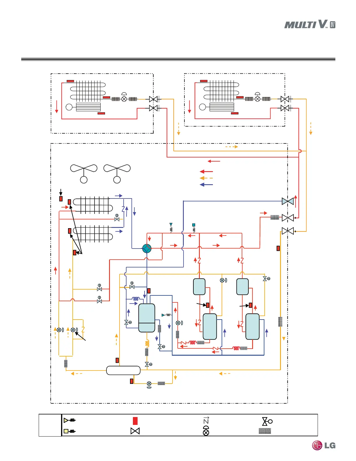
ARUN144BTE4 / 144DTE4,
ARUN168BTE4 / 168DTE4
HEAT PUMP REFRIG. FLOW DIAGRAMS
Upper HEX Defrost Operation
Fan
High Temperature High Pressure Gas
High Temperature High Pressure Liquid
Low Temperature Low Pressure Gas
Accum
Receiver
Outdoor
Temperature
Sensor
Outdoor unit
HEX Temperature
Sensor
Upper
Hot Gas Valve
Low
Hot Gas Valve
Low
Outdoor
EEV
Upper
Outdoor
EEV
Sub-cooling Circuit
Outlet Temperature
Sensor
Liquid Pipe
Temperature
Sensor
Comp1
Discharge
Temperature
Sensor
Comp2
Discharge
Temperature
Sensor
Suction
Temperature
Sensor
Sub-cooling Circuit
inlet Temperature
Sensor
Pressure
Switch
High Pressure
Sensor
4-Way Valve
Low
Pressure
Sensor
Oil Return
Oil
Balance
Receiver
Outlet`
SC suction
Comp1
Vapor
Injection
Comp2
Vapor
Injection
Receiver
inlet
Sub-Cooling
Liquid Pipe
Gas Pipe
Charging port
Active path
Sub-Cooling HEX
Inverter
Comp2
Inverter
Comp1
Oil
Separ
-ator
Oil
Separ
-ator
M
Elec tron ic
Expa nsion Va lve
Fan
Indoor Heat Exchange r
M
Elec tron ic
Expa nsion Va lve
Fan
Indoor Heat Exchanger
MM
ss
Check valve
EEV
Solenoid valve
SVC Valve
Pressure Sensor
Pressure Switch
Temperature Sensor
Remarks
Strainer
 Loading...

