55
Installation Manual
Due to our policy of continuous product innovation, some specifications may change without notification.
©LG Electronics U.S.A., Inc., Englewood Cliffs, NJ. All rights reserved. “LG” is a registered trademark of LG Corp.
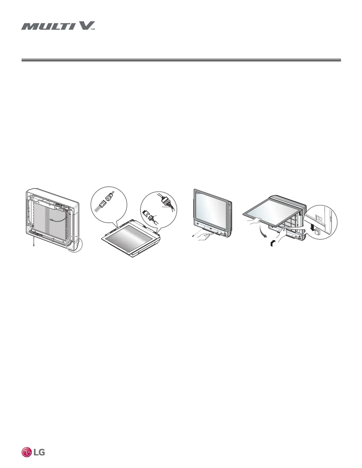
Finishing Installation — Gallery Indoor Units
Before completing installation, the picture and front metal panels of the Gallery indoor unit must be re-installed. Before re-installing, verify
that communications cable and power wiring between the outdoor and indoor units are connected.
1. Check if the side cover is assembled properly, especially if a knockout hole for the piping is used.
2. Verify if the drain hose and refrigerant piping is routed correctly from the side and the rear of unit.
3. Route the power wiring through the indoor unit’s bottom left-hand groove (Step 1).
4. Make the connections to the communication PCB connector, and to the front panel connector (Step 2).
5. Attach the top part of the front metal panel, aligning it with the screw holes at the bottom (Step 3), and then secure the front metal panel
with the factory-supplied screws.
6. Suspend the hooks of the picture panel in the bottom grooves (Step 4).
Comm. PCB
Connector
Front Panel
Connector
Comm. PCB
Connector
Figure 68: Finishing Gallery Indoor Unit Installation
FINAL INSTALL
Gallery Indoor Units
SF Frame
 Loading...