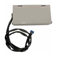
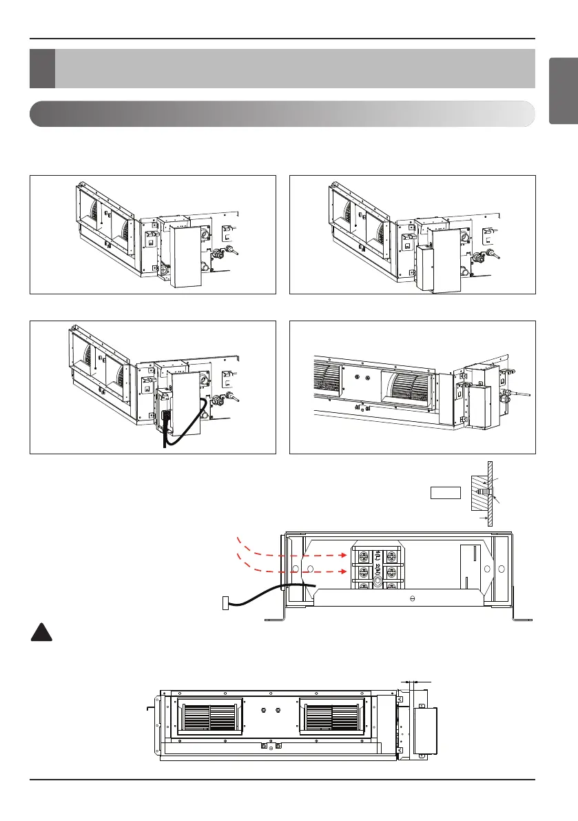
Assembly Diagram
Installation Manual 7
ENGLISH
9/16
Fig. A
Control box cover
screw
Insulation
n High Static Duct
※
Wiring
Note: While connecting the PRARS1, attach insulation at the rear of the
control box cover where it receives screws as shown in Fig. A.
Step1. Open control box cover.
Step2. Assemble PRARS1 with control box cover.
Step3. Open the cover of PRARS1 and connect wires.
Auxiliary Heater communication lines
(under AC24V,over AWG24)
These wires should not make
contact with high voltage lines.
Check the distance between PRARS1 and a control box
when connecting anchor bolts.
To indoor unit PCB
(CN-PTC)
Step4. Assemble control box cover.
(Unit : inch)
Assembly Diagram - PRARS1
3. Assembly Diagram
CAUTION
!