Assembly Diagram
Installation Manual 9
ENGLISH
n 1 Way CST
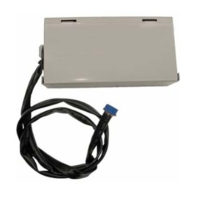
Step1. Open control front panel. Step2. Assemble PRARS1 with cabinet.
Step3. Open the cover of PRARS1 and connect wires.
Step4. Assemble control box cover and front panel.
Fig. A
Control box cover
screw
Insulation
Note: While connecting the PRARS1, attach insulation at the rear of the
control box cover where it receives screws as shown in Fig. A.
※
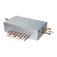
Wiring
Auxiliary Heater communication lines
(under AC24V,over AWG24)
These wires should not make
contact with high voltage lines.
To indoor unit PCB
(CN-PTC)