EasyManuals Logo

LG Therma V AHBW A0 Series User Manual

LG Therma V AHBW A0 Series
75 pages
To Next Page IconTo Next Page
To Previous Page IconTo Previous Page
Page #50 background imageLoading...
Page #50 background image
Trouble Shooting Guide
- 50 -
Copyright ©2013 LG Electronics. Inc. All right reserved.
Only for training and service purposes
LGE Internal Use Only
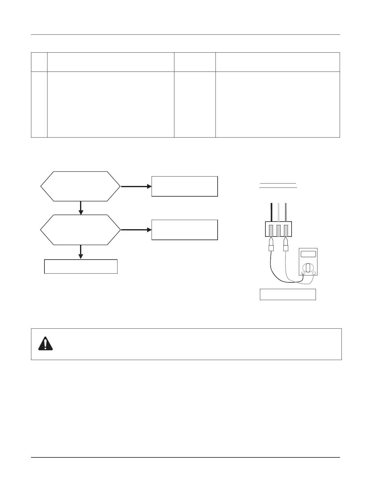
03 Bad communication between control panel
and indoor uni
• Incorrect
connection
between
sensor and
PCB
• PCB fault
• Sensor fault
• Wire connection between control panel
and main PCB 1 should be tight
• Output voltage of PCB should be 12 V DC
Code
No.
Description Cause Normal Condition
n Error diagnosis and countermeasure flow chart
Replace the control panel
Replace main PCB 1
Yes
Yes
No
No
Does the error occur
again when the control
panel is replaced?
Does the error occur
again when the cable
(between control panel
and PCB) is replaced?
Check if the wire is
connected tightly and also
check wire itself
After replacing the control panel or main PCB 1, it is very important to perform parameter setting by ʻentering
Installer Setting Modeʼ at the control panel.
If not, system will NOT be operated correctly. It is STRONGLY recommended to keep above instruction.
Check the Voltage.
Unit
V
12 V DC
12 V
(RD)
S
(YL)
GND
(BK)

Other manuals for LG Therma V AHBW A0 Series

Questions and Answers:

Question and Answer IconNeed help?

Do you have a question about the LG Therma V AHBW A0 Series and is the answer not in the manual?

LG Therma V AHBW A0 Series Specifications

General IconGeneral
BrandLG
ModelTherma V AHBW A0 Series
CategoryAir Conditioner
LanguageEnglish

Related product manuals