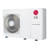
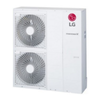
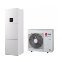
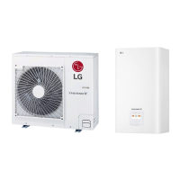
Description
No Name Remarks
1 Entering water pipe PT 25.4mm(Female type)
2 Leaving water pipe PT 25.4mm(Female type)
3 Strainer Filtering and stacking particles inside circulating water
4 Electronic heater Providing additional heating capacity to the water circuit
5 Control box PCB and terminal blocks
6 Plate heat exchanger Heat exchange between refrigerant and water
7 Water pump Circulating the water
8 Pressure gage Indicates circulating water pressure
9 Safety valve Open at water pressure 3 bar
10 Expansion vassel Protecting components from water pressure
11
Main PCB assembly(Inverter)
This PCB controls the cycle parts of the unit
12
Main PCB assembly(Heater)
This PCB controls the functioning of the unit
AHBW056A0/AHBW076A0/AHBW096A0

 Loading...


