Do you have a question about the LG THERMA V AHNW16606B0 and is the answer not in the manual?
Defines informed persons, qualified personnel, and authorized technicians.
Explains warning, caution symbols and general safety instructions.
Guidelines for service procedures, warranty, and product usage.
Crucial safety precautions for unit installation.
Important considerations for installation to prevent hazards.
Key precautions to follow during unit operation.
Advice on installation area, transportation, and disposal.
Essential steps before starting the unit operation.
Technical specifications for the indoor unit.
Important notes and clarifications regarding unit specifications.
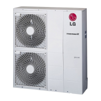
Technical details for specific outdoor unit models.
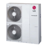
Technical details for specific outdoor unit models.
Technical details for specific outdoor unit models.
Table detailing the functions and availability for indoor units.
Performance curves and control methods for the pump.
Process and Instrumentation Diagram with component legend.
Electrical wiring schematics for the indoor unit.
Detailed list and description of wiring components and terminals.
Wiring schematics for specified outdoor unit models.
Wiring schematics for specified outdoor unit models.
Wiring schematics for specified outdoor unit models.
Visual breakdown of the indoor unit components.
Detailed list of parts for the indoor unit's exploded view.
Visual breakdown of outdoor unit model AHUW146A2.
Parts list for outdoor unit model AHUW146A2.
Visual breakdown of outdoor unit model AHUW096A3.
Visual breakdown for multiple outdoor unit models.
Visual breakdown for multiple outdoor unit models.
General parts list for outdoor units.
Explanation of the model number coding system.
Summary table of model names and their capacities/power.
Detailed step-by-step guide for compressor replacement.
Importance of correct assembly of outdoor panels for protection.
Troubleshooting for supply voltage and controller humidity problems.
Troubleshooting for no water flow and defrost related alarms.
Steps to resolve Module 1 communication or failure alarms.
Steps to resolve Module 2 communication or failure alarms.
Troubleshooting for sensor and thermostat errors.
Troubleshooting for flow, sensor, and RTC fail errors.
Troubleshooting for DHW and inverter module communication issues.
Summary of outdoor unit error codes and their meanings.
Flowchart and methods for diagnosing IPM faults.
Specific procedure for checking IPM on AHUW096A3.
IPM checking steps for specific outdoor unit models.
IPM checking steps for specific outdoor unit models.
Flowchart for diagnosing maximum CT errors.
Procedures for checking CT sensing and inverter PCB signals.
Detailed checks for inverter PCB and CT sensing.
Flowchart for diagnosing DC link voltage errors.
Specific check points for AHUW096A3 regarding DC link and signals.
Check points for various models related to PFCM and pin numbers.
Flowchart for diagnosing DC compressor position errors.
Detailed steps for performing an IPM check.
Procedures for CT sensing and connector checks.
Flowchart for diagnosing AC input instant overcurrent errors.
Specific short check points for AHUW096A3.
Specific checks for other outdoor unit models.
Flowchart for diagnosing inverter compressor overcurrent.
Flowchart for diagnosing high temperature in discharge pipe.
Flowchart for diagnosing low pressure errors.
Flowchart for diagnosing various sensor errors.
Flowchart for diagnosing high pressure sensor errors.
Flowchart for diagnosing PCB communication errors.
Checks for communication issues on specific models.
Detailed checks for communication errors between PCBs.
Flowchart for diagnosing phase errors.
Methods to check for phase loss and reversal.
Flowchart for diagnosing EEPROM checksum errors.
EEPROM checking procedures for specific models.
Flowchart for diagnosing high temperature in condenser pipe.
Flowchart for diagnosing heatsink temperature errors.
Procedures for checking PFCM on various models.
Flowchart for diagnosing fan lock errors.
Fan motor voltage checks for specific models.
Flowchart for diagnosing AC input instant overcurrent errors.
Wiring check points for AHUW096A3.
Wiring check points for specified models.
Wiring check points for specified models.
Tables showing resistance values for pipe and air sensors.
Tables showing resistance values for heatsink and D-pipe sensors.
Procedure to check insulation resistance between compressor and panel.
Method to check the resistance of the U, V, and W phases.
| Type | Air-to-water heat pump |
|---|---|
| Heating Capacity | 16 kW |
| Refrigerant | R32 |
| Noise Level | 45 dB(A) |
| Power Supply | 50Hz |
| Operating Temperature Range (Heating) | -25°C to 25°C |
| Operating Temperature Range (Cooling) | 43 °C |