5 PIPING
Refer to site-specific drawings for general locations of the piping connections. The drawings should
specify where the piping connects to the Liebert DCD.
NOTICE
Risk coil and piping rupture. Can cause equipment damage and major fluid leaks resulting in serious
building damage, expensive repair costs and costly system down time.
Thermal expansion of the cooling fluid without means of expansion can cause the coil and piping to
rupture, spilling cooling fluid in the conditioned space. This can be caused, among other ways, by closing
the ball valves on both the supply and the return pipes. Always allow for thermal expansion either by
leaving at least one of the valves open or by opening the Liebert DCD’s bleed valve (see Figure 5.11 on
page41).
5.1 System Connection Configuration
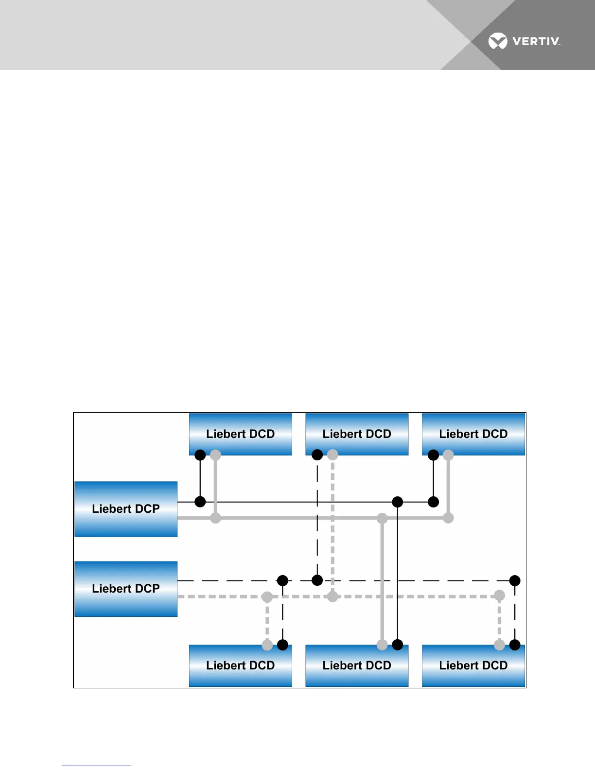
If possible when using a chilled water distribution unit such as the Liebert DCP™, connect the Liebert DCD
in an interlaced configuration (see Figure 5.1 below). In an interlaced configuration, half the cooling
modules in an aisle are connected to one chilled water distribution unit and the other half are connected
to another chilled water distribution unit. Interlacing the connection piping will keep half the Liebert DCD
units operating and maintain cooling in the conditioned space should one chilled water distribution unit
fail.
Figure 5.1 Typical Liebert DCD interlaced piping
Vertiv | Liebert® DCD™ User Manual | 33