Figure 5.4 Typical Liebert DCD non-interlaced piping
5.2 Connection Methods and Points
Refer to site-specific drawings for general locations of the piping connections. For Liebert DCD
connection locations, refer also to Figure 5.5 below andFigure 5.6 on the next page.
The assembly and connection means used for piping the Liebert DCD system are the same as those used
in conventional chilled water systems. Observe all standard practices during installation and startup to
prevent damage and contamination. All piping must be ASTM Type L copper.
The Liebert DCD supply and return piping connection is 1" OD internal threaded copper pipe. Supply and
return pipes are marked by labels on the unit itself. Torque for this connection is 147lb/ft(200Nm).
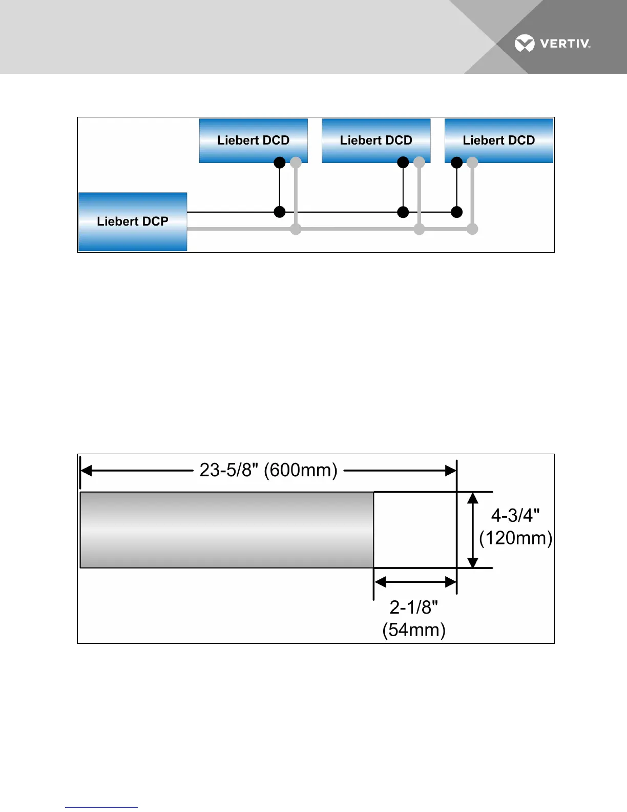
5.3 Floor Cutout Dimensions for Installation with Bottom Connections
Figure 5.5 Floor cutout dimensions, width 23-5/8" (600mm)
Vertiv | Liebert® DCD™ User Manual | 35