Installation and Configuration
15
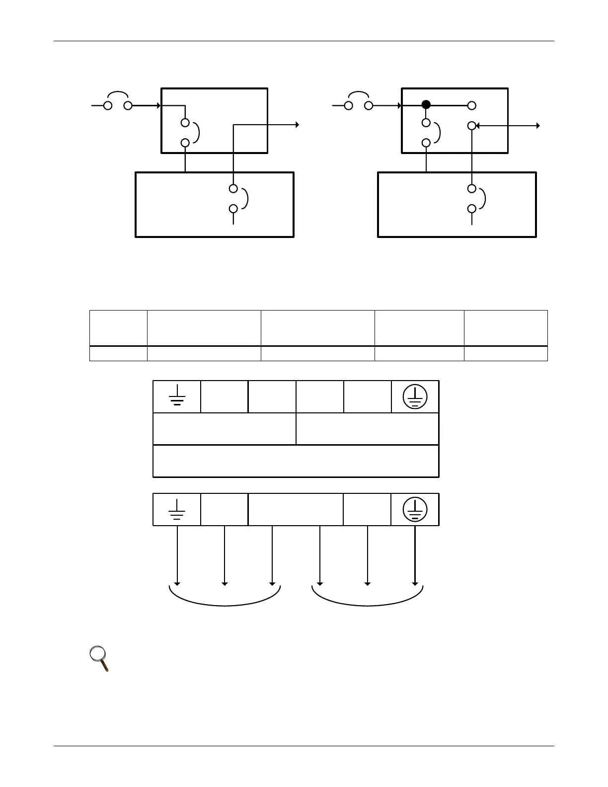
Figure 6 Distribution box electrical connections diagram
PD-CEHDWR and PD-CEHDWRBYP Terminal Block Connections
Conduit entry holes are provided on the rear and side of the box. Input and output wiring should not
share the same conduit.
Table 1 Electrical specifications
Input
Current
Rating
Recommended
(Maximum) External
Overcurrent Protection
Recommended Wire
(Including ground wire)
(758C copper wire)
Maximum Wire
Accepted by
Terminal Block
Terminal
Tightening
Torque
24A 32A 6-10mm
2
(8-10AWG) 10mm
2
(8AWG) 2.26 Nm (20 in-lb)
NOTE
1. Note1 The installer must provide circuit breaker protection according to local codes. The
mains disconnect should be within sight of the UPS or have appropriate an appropriate
lock-out. Maintain service space around the UPS or use flexible conduit.
2. Note 2 The installer must provide output distribution panels, circuit breaker protection, or
emergency disconnects according to local codes. Output circuits must not share a common
conduit with any other wiring.
Mains
Input
Output
Output
Input
CB
Input
CB
UPS
Output
CB
32A
External
Branch
CB
32A
External
Branch
CB
30 30
30 30
UPS - PFC, Battery, InverterUPS - PFC, Battery, Inverter
Byp.
Inv.
PD-CEHDWR PD-CEHDWRBYP
Mains
UPS
Output
CB
Input
NNLL
NNLL
OUTPUT INPUT
32Amp Max Branch
Overcurrent Protection
6-10mm
2
- Use Copper Wire Only
OUTPUT TO LOAD INPUT TO UPS