TECHNICAL FEATURES
LIFE home integration reserves the right to make changes to technical characteristics at any time and without prior notice, without changing its intended
use and function.
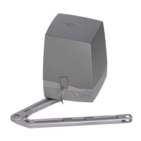
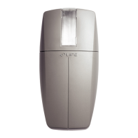
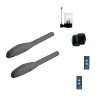
ACER: Irreversible electromechanical operator for sliding gates with optical/magnetic encoder and built-in ECU
Version: ECU – 230 V ac 50 Hz ECU – 24 V dc
AC4 / AC4R AC6 / AC6R AC8 AC4 24 P AC6 24 X AC8 24 X
Built-in ECU RG1A / RG1R RG1A / RG1R RG1A RG1 24 P RG1A 24 X RG1A 24 X
Power supply V 230 Vac 50 Hz
Motor power supply V 230 V a.c. 24 V d.c.
Motor power W 250 280 300 40 80 90
Power input from mains 230V / Max. motor absorption at pick-up 24 V A 1,1 1,2 1,4 5 6 12
Capacitor µF 14 14 16 NO
Thrust N 500 700 900 300 500 700
Lubrication Tipo grease oil grease oil
Thermal protection device °C 140 NO
Limit switch 2 electromechanical or magnetic limit switches in M version
Encoder optical magnetic optical
Speed m/min 10 11
External toothed wheel module 4
Number of teeth external toothed wheel 20 16
Work cycle % 35 80
Nominal work time min 10 20
Battery recharge time (optional)* BATTERY NOT PROVIDED 48
Opening cycles with charged battery* BATTERY NOT PROVIDED 20 15 10
Operating temperature °C from -20 a +70
Protection class IP 54
Motor insulation class F D
Assembly horizontal with dedicated anchorage plate
Dimensions / weight 170 (plate) x 342 x 288 (h) mm / 10 kg
Use in acid, saline or potentially explosive environment no
Max gate weight kg 400 600 800 400 600 800
* for 2 Ah batteries (optional and installed in control unit).
1.0 INSTALLATION
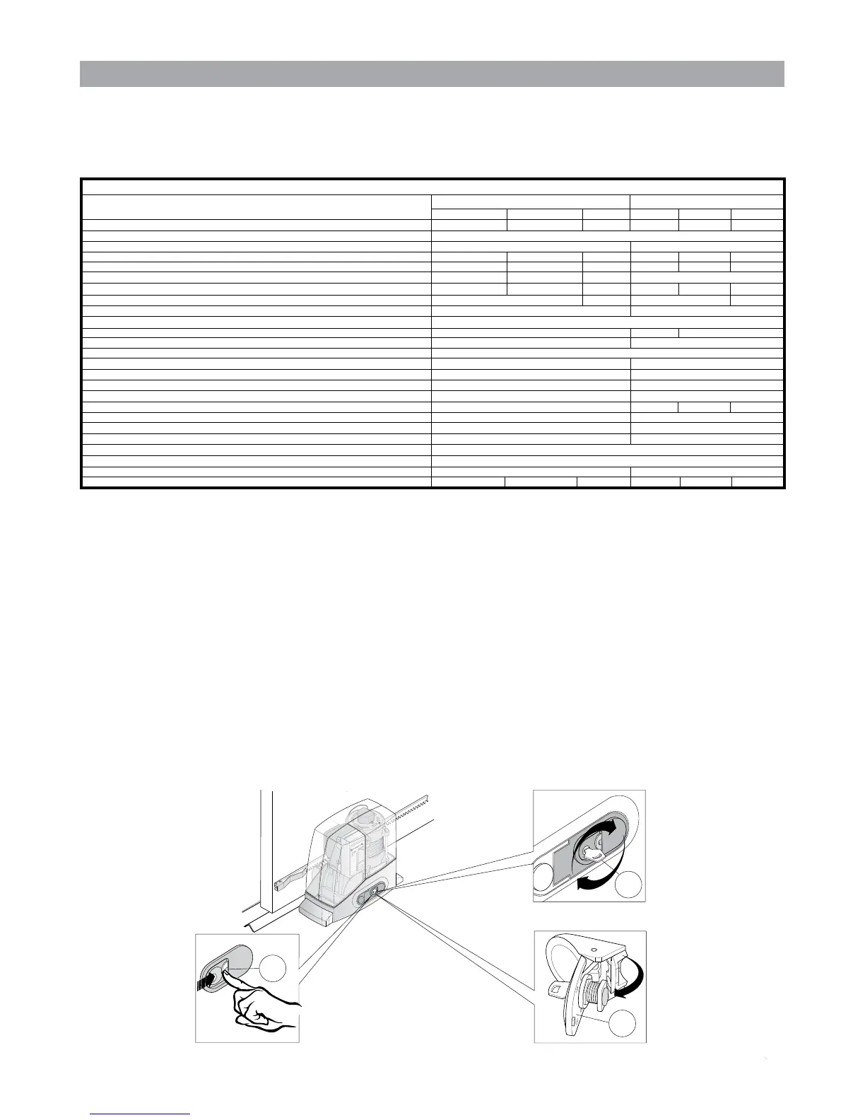
1.1 Operator release
Attention:
• Thettermustpermanentlyxthelabeldescribingthemanualreleaseoperationclosetothemanualreleasekey.
• T
he activation of the manual release could cause an uncontrolled movement of the gate in the event of mechanical damage or unbalanced conditions.
• Beforeperformingthemanoeuvreswitchofftheelectricitysupplytotheautomation.
• Toavoidbreakingthekey,donotapplyexcessiveforce.
a) Slide the lock protection cover (1). See g. (1.1).
b) Insert the key (2) in the lock and turn to the right through 90°.See g. (1.2).
c) Gently pull the key outwards until thehatchisprotruding,thenpulloutwardsuntilitstops.Seeg.(1.3).
d) T
he operator is now free and can be moved by hand. A microswitch assembled on the blockage device prevents the motor from operating when
the power comes back on.
e) Toreconnectthetransmission,turntheoppositewayandmovethegatemanuallyuntilithitchesup.
Figure (1)
AC017
3
2
1
Fig.1.2
Fig.1.1
Fig.1.3
 Loading...