1.2 Installing operator components: positioning and installation of the anchorage plate
The area in which the operator is installed must provide adequate space for performing maintenance and manual release operations.
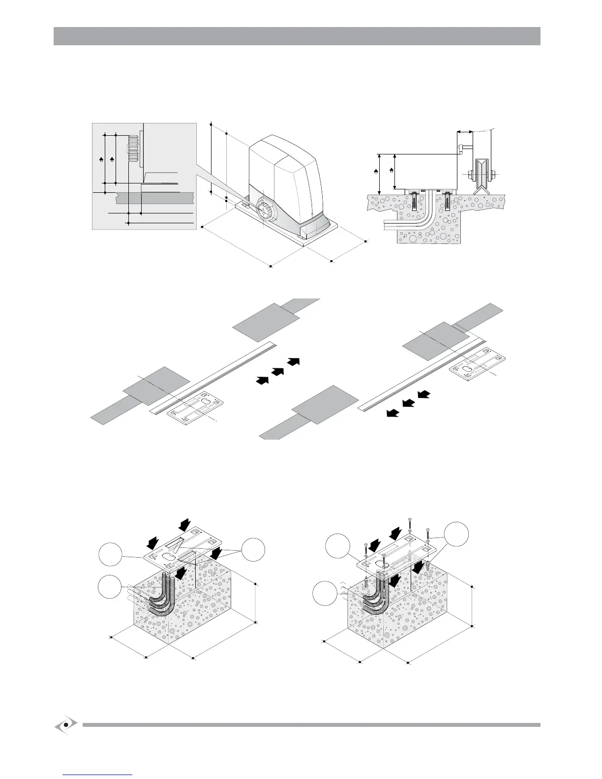
a) Adhere to the dimensions in g.2.
Fig. (2)
335
51
170
582
003
22
170
192
59 61z
99 81z
15
AC003a
88 61z
19 81z
38
Fig. (3)
b) Observe the orientation in g. (3) for positioning the operator anchorage plate (R – L).
c) Refer to g. (2.2) for the respective heights for 16 or 18-tooth pinions.
d) Lay the electric cable pipes (4), allowing them to protrude and plugging them to prevent them from lling with debris.
F
asten the anchorage plate (1) to the concrete base with 4 expanding screw anchors (2), see g.(4.2); or sink in the fresh concrete folding the two
“L”s (3), see g.(4.1).
Fig. (4)
1
4
350
250
200
3
AC005
2
1
AC010
4
350
250
200

 Loading...