Do you have a question about the Life GE UNI R and is the answer not in the manual?
Provides essential instructions and warnings for the proper installation, usage, and upkeep of the GE UNI R control unit.
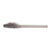
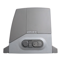
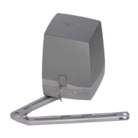
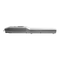
Details the components and devices included in a typical GE UNI R automation setup.
Lists the items contained within the GE UNI R control unit packaging.
Illustrates the electrical system and shows the various terminal connections for the control unit.
Details the first phase of installation involving stop plate adjustments and leaf positioning.
Guides through the process of initialising the control unit, including specific steps for single operators.
Describes the identification process for staggering and opening stop plates for leaf 1 and leaf 2.
Explains how to adjust mechanical stop plates for the Ergo system, focusing on closure and opening.
Covers the initial installation phase when using electric stop switches for gate automation.
Details the control unit initialisation process when electric stop switches are employed.
Outlines the procedure for identifying staggering and opening stop plates when electric stop switches are used.
Lists essential preliminary checks to be performed before commencing wiring and connection work.
Details the terminal connections on the right hand side of the control unit for various devices.
Describes the terminal connections on the lower part of the control unit for power supply and encoder connections.
Explains the layout and function of the control unit's membrane keyboard for setting operations.
Procedure for identifying a radio control for the STEP command function.
Instructions on how to reset all previously identified radio controls from the system.
Guides the initialisation process for operators that do not use electric stop switches.
Details how to adjust the force value when the gate is immobile or struggling to move.
Explains the procedure for identifying direction, travel, and speed for operators equipped with electric stop switches.
Describes the process for initialising the control unit, erasing previous settings and defining the automation.
Details the procedure for erasing travel values and function modes from the control unit.
Explains the '2-step automatic' function mode for gate automation, enabling automatic closure.
Details how the control unit reacts to temporary power failures based on the leaf's position.
Describes how to set functions for inputs 6-7 and 6-11, such as PHOTO, PHOTO 1, PHOTO 2, STOP, and PAUSE.
Explains how to regulate the operator's thrust and speed using the FORCE function.
Regulates the distance travelled by the gate during deceleration in the final stages of opening and closure.
Provides instructions for checking and replacing the frontal fuse on the operator control unit.
Details how control unit LEDs indicate malfunctions and suggests possible solutions.
Provides essential safety and installation guidance specifically for professional installers.
Outlines the essential steps and checks for testing the gate automation system for safe operation.
Specifies the instructions and warnings that must be followed for the proper maintenance of the automation.
| Maximum Leaf Length | 3 m |
|---|---|
| Maximum Gate Width | 3 m |
| Motor Voltage | 24 V DC |
| Operating Voltage | 24 V DC |
| Safety Features | Obstacle detection |