Before commencing wiring and connection work, read the SAFETY INSTRUCTIONS AND WARNINGS and INSTALLATION INSTRUCTIONS
ll wiring and connection operations must be carried out with the control unit disconnected from the electricity supply (and from the buf
er battery if present); if the disconnection device is not in view, display a sign reading “ATTENTION: MAINTENANCE WORK IN PROGRESS”.
fer battery if present); if the disconnection device is not in view, display a sign reading “ATTENTION: MAINTENANCE WORK IN PROGRESS”. f
Before proceeding with installation, the following preliminary checks must be performed on the gate and installation area:
he area in which the control unit is installed must not be prone to fl ooding: it is therefore forbidden to install it excessively close to the ground. The optimal
height is between 80 and 150 cm from the ground, the minimum 40cm.
2) The installation area should be as sheltered as possible from atmospheric agents and must allow the fi tter good accessibility for installation and subsequent work.
he surfaces on which the GEBOX is mounted (column, pillar, wall, etc.) must be smooth and vertical, and adequately solid and compact to allow secure fastening.
GEBOX container installation
a) Remove the cover and hinge from the GEBOX and decide on the mounting position, verifying that:
it is at least 40 cm from the ground;
the outlet of the pipe housing the electric cables is just below the container.
Mark the centres of the four clamping screws and make holes for the screw anchors.
c) Place the screw anchors inside the holes, rest the container against the wall and fasten securely using suitable screws.
d) Carefully clean the inside of the container to remove any plaster dust or other residues.
e) Fit the hinge into the dedicated recess on the left or right side of the container.
f) Fit the cover onto the hinge then rotate to close it.
g) Lock the lid by tightening the two screws in the holes in the corners on the opposite side to the hinge.
h) Assemble the four screw cover inserts on the corners of the cover.
In order to facilitate control unit wiring or programming, it can be pulled out of its housing without requiring the use of tools.
a) Push the control unit upwards to release the clips and pull outwards.
b) Compatibly with the length of the cables, rest on the edge of the container or hold.
Once the wiring and/or programming work is complete, place the control unit back in its recess by pressing lightly until the 4 clips snap in.
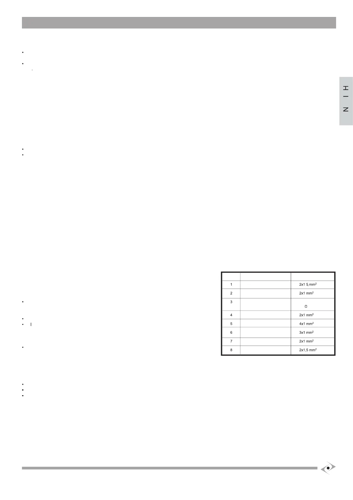
epending on the installation, the type and quantity of devices installed, the cables required may vary. The table below shows the cables needed for a typical installation.
The cables used in the installation must be IEC 60335 compliant.
ATTENTION: the cables used must be suited to the type of installation. It is the Fitter’s
responsibility to choose appropriate material.
ll wires must be unsheathed as little as possible (6mm at the most) and as close as possible
o the connection terminals, in order to prevent accidental contact with live parts in the event
that cables disconnect from the terminals.
Do not pre-seal cables to be fastened to the terminals using screws.
f it is possible that wires subject to voltage higher than 50 Volt RMS and very low voltage
afety wires may come into contact with one another, wires with voltage higher than 50 volt RMS
ust be insulated with a sheath; or the very low voltage safety wire must have an insulating
sheath at least 1mm thick.
All external connection cables must not be of the fl at twin tinsel cord type.
Setting up the electric system and connection to the mains supply
This manual does not describe how the electrics system should be prepared for connection to the mains. It does, however, give the following warnings:
The electricity supply line must be installed and connected by an authorised electrician or professional fi tter.
The electricity supply must be adequately protected against short circuits and static discharge.
he power supply network must contain an omnipolar disconnection device with an opening distance of the contacts equal or greater
than 3.5 mm that assures the complete disconnection of the power supply.
Introducing the electric wires into the GEBOX
pen the required pre-punched holes in the bottom of the container (remembering that it is compulsory to keep 230V wires separate from those with
b) Position cable glands suited to maintaining the degree of protection of the container inside the holes.
c) Pass the wires needed for the connections through the cable glands, leaving an additional length of approximately 40 cm
d) Carefully close the cable glands and seal the ends of the tubes with silicon in order to prevent access to insects and/or dirt.

 Loading...