edestrian command identifi cation
fl ash slowly and the fl ashing light will emit double fl ashes.
on the radio control(s) (not master) that
one wants to identify and hold down until the green LED
and the SPLENDOR fl ashing light light briefl y.
will fl ash alternately and the fl ashing light will emit a
on the radio control(s) (not master) that
ne wants to reset and hold down until the green LED and
fl ashing light light briefl y.
All the operations performed by the operator and gate during travel recognition are the Fitter’s responsibility.
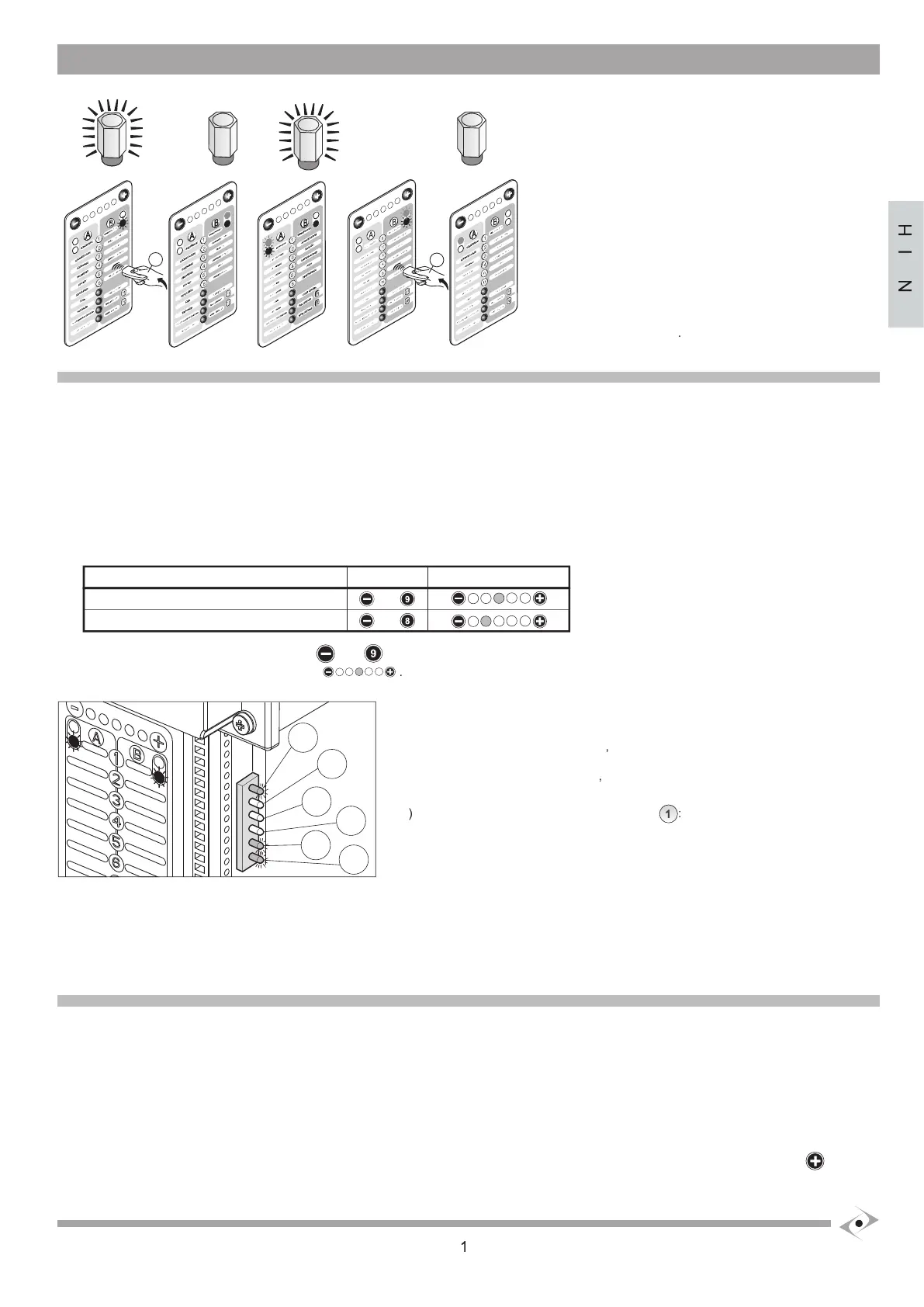
ATTENTION: LIFE cards are multipurpose and may be used for several applications; therefore, on activation they require the identifi cation of
the type of automation that they will serve.
stop plates or check the stop plates, position the leaf approximately 45° from the closure position.
c) Follow the indications in the table below for the various types of operator:
, together, and holding them down, switch on the power supply to the control unit.
Release the keys when the third red LED lights:
Check that the 2 red LEDs fl ash.
Check that the lateral LEDs ,
Check that the lateral LEDs
eing a single leaf system, staggering will not be indicated for the manoeuvres below.
ATTENTION: if a single motor application with electric stop plates is used, connect the stop plates to the motor 1 terminals:
34-32 and 33-32; jumper the motor 2 stop plate inputs: terminals 31-32 and 30-32.
If this does not occur, check the connections and effectiveness of the various devices, assure that the NC inputs for which no device is connected
Operators without electric stop switches: direction, travel and speed identifi cation
The direction and travel identifi cation phases are performed at reduced speed.
LEAF 2 CLOSURE STOP PLATE IDENTIFICATION:
, holding it down until leaf
slowly reaches and pushes for a few seconds against the closure stop plate. Press
the stop plate: the red led
will light. When the leaf
has identifi ed the closure stop plate the red LED
APPLICATION
WITHOUT ELECTRIC STOP SWITCHES
WITH ELECTRIC STOP SWITCHES
KEYS
+
+
HORIZONTAL LEDS
 Loading...