5
3.0 WIRING AND CONNECTIONS
• Before commencing wiring and connection work, read the SAFETY INSTRUCTIONS AND WARNINGS chapter carefully.
• The operator must be connected to Life control units only.
• All wiring and connection operations must be carried out with the control unit disconnected from the electricity supply. If the
disconnection device is not in view, display a sign reading: “ATTENTION: MAINTENANCE WORK IN PROGRESS”.
• The internal wiring of the linear electromechanical operator performed by the Manufacturer, may not be modied under any circumstances.
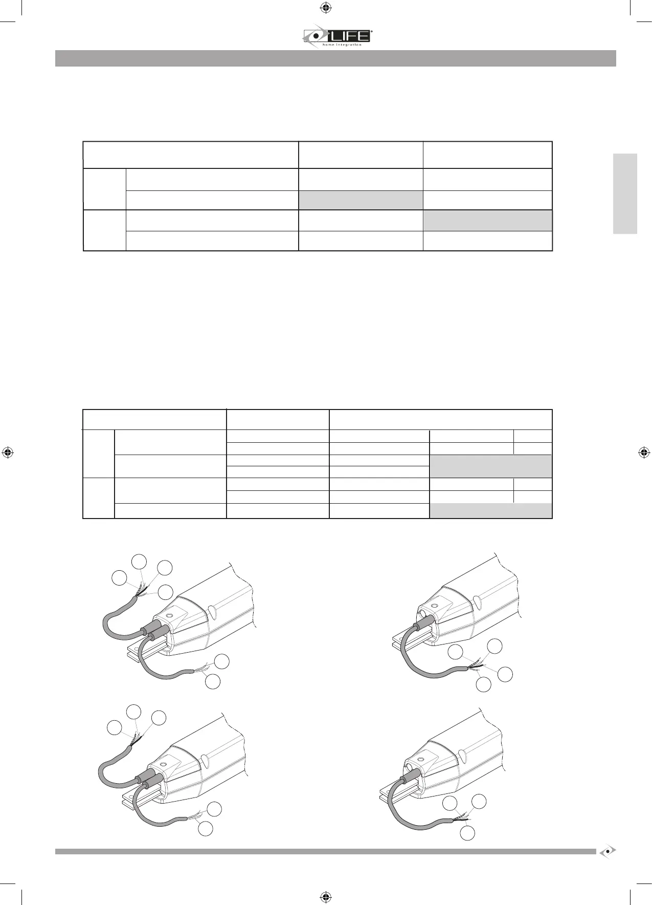
3.1 Electrical connections of the operator
One or two cables lead out of the operator depending on whether or not one has the UNI version.
The U
The 230 V and 24 V two-cabled versions have an extra cable for the encoder and limit switch signal (2-wired cable).
The 230V models come with a capacitor, which is housed in the control unit. The capacitor is connected in parallel to the “open motor” and “close
motor” cables.
N.B. each cable is 1m long.
OP3 - OP3L - OP5 - OP5L
OP3 UNI - OP3L UNI - OP5
UNI - OP5L UNI
OP324 - OP524
OP324 UNI - OP524 UNI
230 V
50 Hz
24 V
LIMIT SWITCH and ENCODER SIGNAL
MOTOR POWER SUPPLY
BLUE/ GREY COMMON BROWN +
BLACK OPEN MOTOR BLUE -
BROWN CLOSE MOTOR
YELLOW - GREEN EARTH
BLUE + BROWN +
BROWN - BLUE -
YELLOW - GREEN EARTH
OP3 - OP3L - OP5 - OP5L GE1A -GE2A GE1R -GE2R
OP3 UNI - OP3L UNI - OP5 UNI - OP5L UNI GE UNI R
OP324 - OP524 GE1A 24 GE1A 24-GE2A 24
OP324 UNI - OP524 UNI GE UNI 24R
230 V
50 Hz
24 V