Netlink Installation and Operation Manual
6 7
Installation and Operation
1.3.4 Connecting the Current Sensor(s)
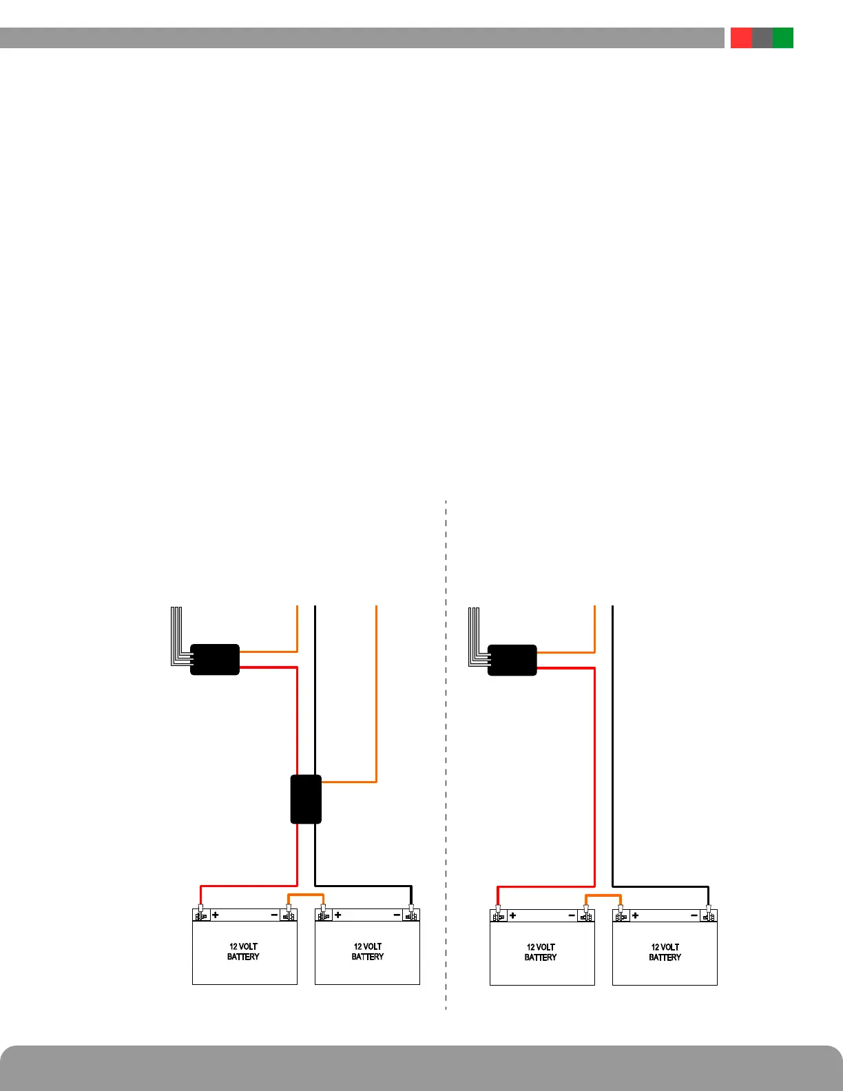
Typically, the current sensor is used to measure battery dis-
charge current to allow battery testing and utilization of the
Battery Condition bar graph. In this application, the short
orange lead connects toward the power supply and the long
red lead connects toward the battery. See Figure 1.6 for
wiring details.
If not using the current sensor for the battery, connect the
Current Sensor in-line with the device(s) to be monitored.
To read current in the correct polarity, the positive current
should flow from the longer (red) lead to the shorter (or-
ange) lead on the current sensor. If current is being dis-
played in the opposite polarity than expected, swap the
short/orange and red/long leads.
After connecting the red and orange leads, connect the
white cable to the "Cx" connector that matches the device
number of the power supply (H1 or H2 on Gen 1 boards)
on the Netlink.
1.3.5 Connecting the Event Input
Connect one end of the Event cable to the Event1 connector
on the Netlink board and cut off the connector at the other
end of the Event cable. Connect the red and black wires to
the voltage to be monitored. If monitoring a relay or switch
contact (a common example would be the tamper switch
of the enclosure), an external voltage must be run through
the contact. Set the Event1 Input Invert Jumper as required.
Example:
To monitor the NC tamper switch in an LSP enclosure, con-
nect a positive voltage (from the FPO power supply or dis-
tribution board) to one lead of the tamper switch. Connect
the other lead of the tamper switch to the red (positive)
lead of the Event cable. Connect the black (negative) lead of
the Event cable to the negative (DC Common) of the voltage
source. (Figure 1.7) Since we want to cause an alert on the
removal of voltage, leave the Event1 Input Invert Jumper OFF.
12 VOLT
BATTERY
12 VOLT
BATTERY
BDM
Current
Sensor
To NetLink
Current Sensor
Input
To FPO
Battery
Terminals
Sense Wire
To FPO DC1 +
Terminal
Short Wire
Long Wire
With BDM Without BDM
12 VOLT
BATTERY
12 VOLT
BATTERY
Current
Sensor
To NetLink
Current Sensor
Input
To FPO
Battery
Terminals
Short Wire
Long Wire
Figure 1.6 - Current Sensor Wiring (Battery Discharge Current)
 Loading...
