Netlink Installation and Operation Manual
2 3
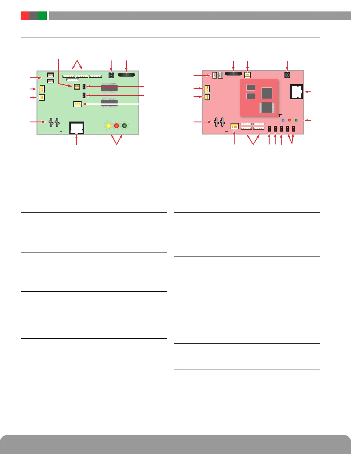
Installation and Operation
1.2 Netlink Network Communication Module Overview
1 C1 through C4 (H1/H2) Inputs (J12,J16,J19,J23)
These are the connectors for the current sensors. Only a Net-
Link current sensor should be plugged into this connector.
The sensors have a range of +/-20A and are typically used to
monitor battery discharge current. See section 1.3.4
2 Event 1 Input (J14)
This is the connector for the Event1 input. This input will
accept 9-30VDC to initiate an event alert. This input will only
indicate an active or inactive condition and will not measure
the voltage level. See section 1.3.5
3 ADC1 Input (J15)
This is the Analog to Digital Converter (ADC) input, which
acts as a voltmeter. It accepts 0-30V and is used to mea-
sure positive or negative system voltages which are common
grounded with the Netlink board. The ADC cable wiring must
be routed away from high voltages. See section 1.3.7
4 Input V+ & V- (J1 [NLX] or J1&J3 [NL2/NL4])
This is the power input for the Netlink board. This input ac-
cepts 8 to 30VDC ONLY from any power supply. If the Netlink
is being used in an FPA series system, an NS2 board is re-
quired to convert the AC power to DC power. See Appendix 2.
Note - The voltage input of the Netlink must be connected
directly to the DC1 output or to the V+/V- fastons (if present)
of the power supply.
5 Ethernet Connection (SK1)
This is the RJ45 jack for the network connection. The ethernet
cable is plugged into this jack. See section 1.3.2
i NOTE: This port does not accept PoE power. Do not con-
nect PoE to this port.
6 Status LED Indicators (D2, D3, D4)
These LEDs indicate the status of the Ethernet link to the
Netlink board.
LED Indicator:
Green (LINK) Lights when Netlink is connected to a network
Red (DATA) Flashes during data transfer
Blue (SYS) Lights when the Netlink is fully booted up and
running. During the bootup process, this LED may flash
on and off several times. The Netlink will not be able to be
accessed until this LED lights steady. Older NetLink boards
may have a Yellow SYS LED.
7 External Temperature Sensor
This connector is for the external temperature sensor and is
only present on the NL4 and NLX boards. See section 1.3.6
8 Dual ADC Jumper (J9)
This jumper enables "Dual ADC Mode" when using the Netlink
with an NS2 board. If an NS2 board is not being used, leave
this jumper OFF.
The following are basic Netlink board descriptions. Refer to the appropriate section for more detailed information.
NOTE - There are two generations of NetLink NL2/NL4 boards. Generation 2 can be identified by the red PCB color, while
Generation 1 uses a green PCB. Use the appropriate illustration above.
RJ45
Input
Event 1
Reset
SYS DATA LINK
V V
+
ADC 1
J10
J18
H1
H2
Device 3
Device 4
Device 2
Device 1
J9
J8
Generation 1 Generation 2
Input
Reset
J10
J18
C1C2
Device 3
Device 4
Device 2
Device 1
J9J8
RJ45
V V
+
Event 1
ADC 1
SYS DATA LINK
J19
NL2 / NL4
 Loading...
