Netlink Installation and Operation Manual
2 3
Installation and Operation
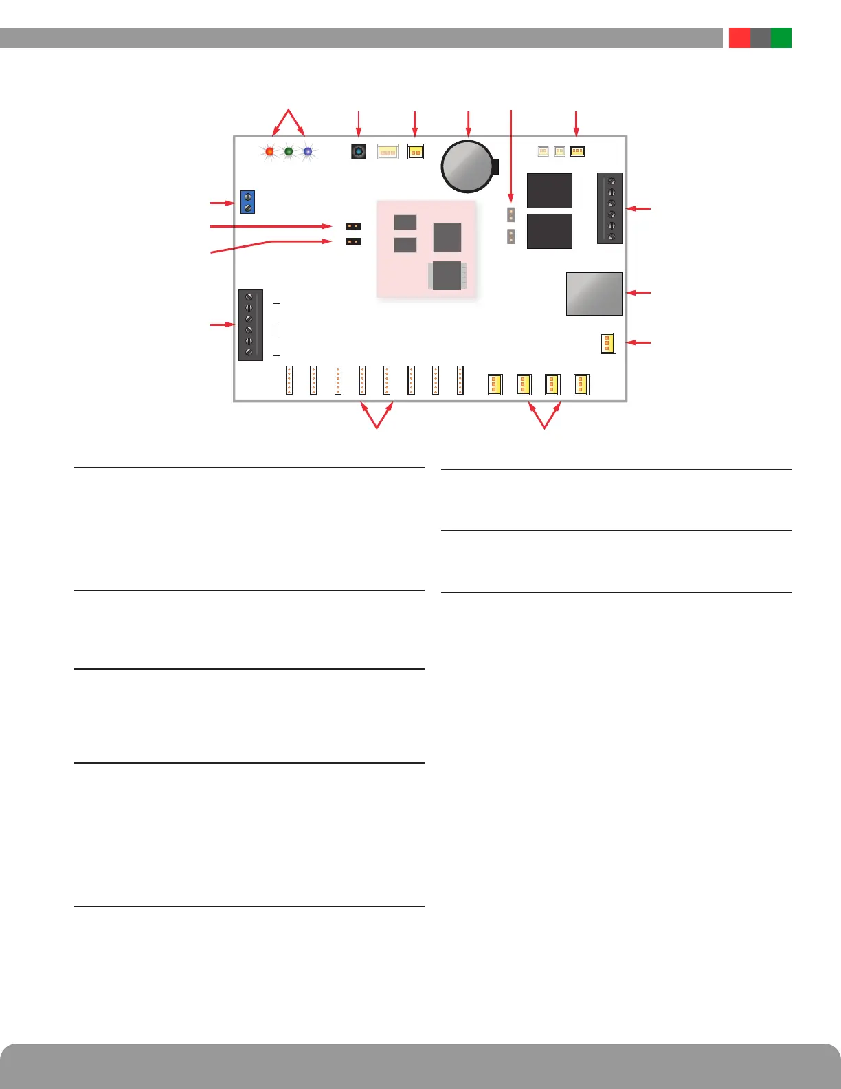
9 Event1 Input Invert Jumper (J8)
This jumper inverts the action of the Event 1 Input. See sec-
tion 1.3.5
Jumper Position:
OFF Event 1 active when voltage is applied
ON Event 1 active when voltage is removed
10 Backup Battery (BT1)
This is the coin cell battery for maintaining the clock when
all power is removed from the Netlink. The battery type is
CR2032.
11 Factory Reset Button (SW1)
This button resets the User Name, Password, and IP Address
settings back to factory default. Typically used when IP and/or
login information has been lost. See section 2.2.1.1 for more
information.
12 Device 1 - Device xx (J4,J5,J6,J11,J17,J24,J25,J26)
Data is passed between the Netlink board and it's connected
devices through these Device serial port links. The NL2 has
two serial ports to monitor two power supply boards. The
NL4 has four ports to monitor up to four devices (maximum
combination of two power supplies, three M8). The NLX has
eight links for up to eight devices. Power supplies 1-4 must
connect to Device 1-4 respectively. See Section 1.3.3.
13 Control Outputs (J10 [NL2/NL4] or TB5 [NLX])
This connector is for the two control outputs. On the NL2 and
NL4, these outputs are open collector (transistor) low-current
outputs for use with RB Relay Boards or other low-current
inputs. On the NLX, these are form C relay outputs, labeled
on the PCB. The Control Output cable wiring must be routed
away from high voltages. See Section 1.3.8
14 Enable 100Mbps (J19)
If present, this jumper enables 100Mbps speed for the net-
work connection.
15 Future Use (J20 & J22)
If present, these jumpers are reserved for future use and
should be left OFF.
16 RS485 Port
The RS485 port allows the connection of up to 16 additional
devices to the NLX. The connected devices must be Genera-
tion 2 FPO or M8 modules with the optional RS485 module
installed (RSMOD).
RS485 Terminals:
A Signal Line A
B Signal Line B
GND Ground
There are two sets of RS485 terminals to allow two branches
from the NLX. These may be used interchangeably. See Sec-
tion 1.3.9 for more details on the RS485 port.
NLX
DC
Reset
NO
Device 1
J9
J8
Event 1
ADC
SYSDATA LINK
Device 2
Device 3
Device 4
Device 5
Device 6
Device 7
Device 8
Current
Sensor 2
Current
Sensor 1
Current
Sensor 3
Current
Sensor 4
RJ45
Battery
NONC NCC C
Temp
GND A B GND A B
RS485 RS485
 Loading...
