Lighthouse ApexRemote Operating Manual
4-6 248083447-1 Rev 1
Communicating
with
ApexRemote
PoE Instrument
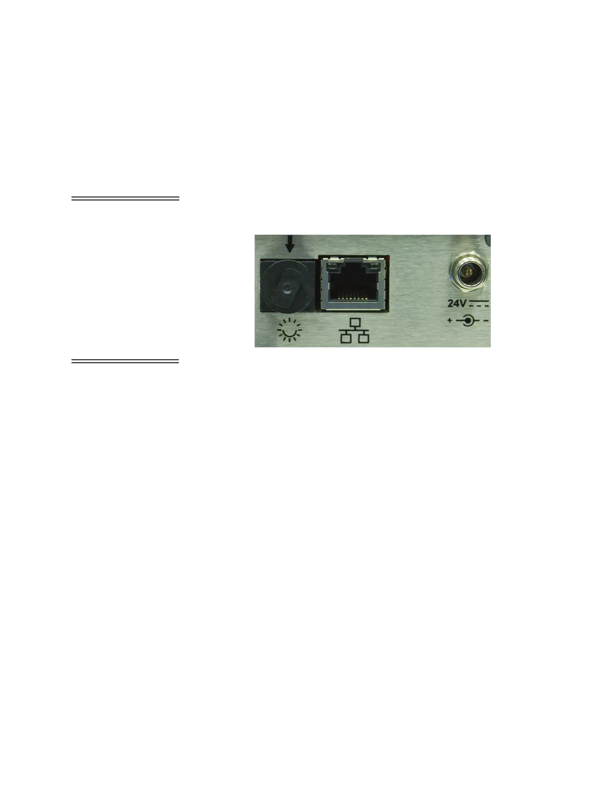
ApexRemote PoE Communications
The ApexRemote PoE eliminates the need for an external power
supply by getting its data and power via its connection to a PoE switch.
This allows a convenient installation because only one CAT6 cable is
required. It can also use a non-powered Ethernet connection with an
external 24VDC power supply. Figure 4-3 shows the ApexRemote
PoE SmartPort, PoE/Ethernet RJ45 and Power Input jack.
WARNING:
The
ApexRemote PoE can
use a standard Ethernet
Cat6 cable and separate
power supply, which
connects to the round
connector shown in
Figure 4-3. The symbol
shows the voltage and
polarity of supplied
power. Handle with care
and keep the connector
away from water or
conductive liquids.
Figure 4-3 ApexRemote PoE Connectors
Note: Category 6 (CAT6)
(22AWG) must be used
when cabling facilities for
PoE devices such as the
ApexRemote.
Setting up the ApexRemote for use on an Ethernet LAN requires
knowledge of the network’s topology and access to network
components to which most users do not have access. It is advisable that
the local IT administration group be contacted and get involved to
ensure greater success.
The ApexRemote should be set up with a static IP so the software to
hardware interface is less complicated. Instrumentation networks need
to have addresses predefined so the measuring devices can always be
found and their data can be reliably transferred to the management
software.
The Instrument Setup Tool User Interface is shown in Figure 4-4.
The COM port assignment is established when the cable is plugged into
an available USB port and FTDI drivers have been installed on the
configuration computer.
Review the upper screen and note the options available. The screen
items are addressed starting on page 4-8. The top sections set up or
adjust the settings needed for the ApexRemote with some items
requiring extra care and advice from the IT group before making the
changes.
 Loading...