Lighthouse REMOTE-4PN Series Operating Manual
3-10 248083317-1 Rev 4
If the Inlet tubing is run over walls or around corners, keep the bend
radius greater than ninety degrees and three feet.
Do not patch sections together and keep the tubing supported to prevent
sagging and kinking over time.
Typical installations use a short length of tubing and a barbed ISO
probe that is either handheld or supported on a tripod.
Connecting the tubing to the instrument Inlet requires removing the cap
from the Inlet connector and installing the ferrule and nut assemblies
on the tubing as shown in Figure 3-14. This may be done with the
Outlet connector, as well, if the pump output requires that it be
exhausted to another area. The procedure is the same for the Outlet.
Figure 3-14 Nut and Ferrule Installed on Tubing
Connect
Interface and
Power Cables
After the ethernet and AC Power cables have been completed, they are
ready for connecting the REMOTE-4PN Series to AC power and data-
gathering equipment. Proceed as follows:
Connections
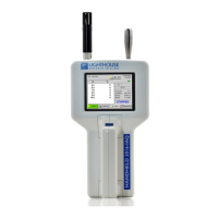
The top of the instrument has the inlet line, which supplies sample air
to the sensor. Using the compression fittings is required to allow wipe-
down of the instrument. See Figure 3-15.
Figure 3-15 Instrument Top Connections
Inlet