Do you have a question about the Lighthouse SOLAIR 3350 and is the answer not in the manual?
Explains the different typefaces used in the manual for clarity.
Provides contact information for service and support.
Details on warning classifications and general safety advice.
Information regarding the product's Class 1 LASER classification.
Precautions against electrostatic discharge (ESD) damage.
Important warnings about connecting multiple interfaces simultaneously.
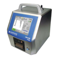
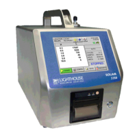
General description of the SOLAIR 3350/5350 and its features.
Details on the instrument's touch screen and data storage capabilities.
Technical specifications for the SOLAIR 3350 model.
Technical specifications for the SOLAIR 5350 model.
Guidance on initial inspection of the instrument upon receipt.
Procedure for unpacking and checking the instrument and components.
Instructions to verify all items against the shipping list.
Detailed steps for returning the unit to the factory for service.
List of optional and standard accessories available for the instrument.
Step-by-step guide for installing the instrument's optional batteries.
Introduction to setting up the counter and analog sensors.
Details on connecting and configuring up to four 4-20mA analog sensors.
Procedure for setting up analog sensors in the instrument's configuration.
Pin-out details for the Peripheral Interface Connector (PIC).
How to use the REPORTS screen to meet specific reporting requirements.
Details on classification requirements for Fed Std ft3 reports.
Information on the EU GMP 2009 standard and its application.
Steps to configure the instrument's Ethernet settings via DHCP or static IP.
Using Lantronix DeviceInstaller to configure IP address and subnet.
Configuration of Ethernet port settings using different cable types.
Detailed instructions for programming the interface using Telnet.
Overview of available communication modes for the SOLAIR.
Introduction to the instrument's communication ports and their usage.
Details on establishing Ethernet connectivity using MODBUS TCP/IP.
Pinout details for the RJ45 connector used for RS232/RS485.
Information on using RS485 for instrument communication.
Using a USB to RS232 converter for RS232 communication.
Overview of point-to-point communication via the USB port.
Step-by-step guide to connect the instrument to a PC via USB.
Instructions for using a USB flash drive for saving reports.
Initial steps to start using the SOLAIR particle counter.
Explanation of the touch screen interface and menu tree.
Overview of the MAIN screen displaying instrument status and options.
How to select and manage locations for sampling.
Description of the two different zoom views for data display.
Enabling the display of both Differential and Cumulative data simultaneously.
Overview of the main configuration screen and its options.
Configuration options for data collection parameters.
Enabling or disabling particle channels for data collection.
Setting up and configuring analog channels for sensor input.
Displaying analog sensor data on the MAIN screen.
Viewing analog data in a zoomed format.
Configuring sample time and number of samples.
Configuring instrument count modes and data formats.
Description of available counting modes: Auto, Manual, Beep, Concentration.
Setting up the instrument for Geiger Counter Mode beeping.
Explanation of Differential and Cumulative particle data display.
Enabling and configuring particle alarms for specific channels.
Setting the alarm threshold value for particle channels.
Procedure to clear the instrument's data buffer.
Options for adjusting instrument operation and settings.
Setting the instrument's date and time.
Adjusting visual and sound settings, language, and startup functions.
Configuring the instrument to automatically start sampling upon power-up.
Enabling display of only the first channel's data.
Enabling real-time MODBUS output with specific configuration settings.
Configuration of pump ramp-up time at the beginning of samples.
Changing the instrument's operating language.
Setting the instrument's communication address for network identification.
Selecting output destination for reports (USB or Printer).
Common printer issues and their resolutions.
Restricting access to instrument functions via password protection.
Enabling a password required upon instrument power-up.
Enabling a password to prevent unauthorized access to configuration settings.
Access to service-related functions, reserved for authorized providers.
Displaying instrument firmware versions and status information.
Saving and managing instrument settings for sampling and reports.
Setting up and managing up to 200 alphanumeric locations.
Viewing stored data records in the instrument's buffer.
Options for printing buffer reports, including summaries and formats.
Printing the currently displayed record from the data buffer.
Selecting a range of records to print from the data buffer.
Printing Cleanroom Classification to Standards reports.
Enabling reports feature and configuring basic report parameters.
Guide to configuring the instrument for specific reports like FED STD FT3.
Directing report output to a thermal printer or USB flash drive.
Steps to print a report after collecting necessary samples.
Details on minimum requirements for Fed Std ft3 reports.
Information on battery life indicators and power shutdown features.
Introduction to programming the SOLAIR using MODBUS Protocol.
Connecting the unit to a PC COM port for programming.
Pinout details for the RJ45 connector used for RS485 communications.
Considerations for attaching the instrument to an RS485 network.
Using a USB to RS232 converter for RS232 communication.
Overview of point-to-point communications via the USB port.
Steps to connect the instrument to a PC using the USB port.
Setting up the instrument to use the MODBUS protocol.
Procedure to set the instrument's real-time clock.
Modifying core instrument parameters like Location, Sample Time, etc.
Explanation of manual and automatic counting modes and action commands.
Overview of routine maintenance for the SOLAIR particle counter.
Reminder to read safety warnings before performing maintenance.
General guidance on when maintenance procedures should be performed.
Recommendation for annual recalibration by an authorized service provider.
Procedure to check the counter for zero counts using a purge filter.
Steps to perform if the instrument fails the Purge Count test.
Table listing default configuration values for the instrument.
Required communication settings for using MODBUS with Lighthouse counters.
List of supported MODBUS commands and their descriptions.
Overview of instrument registers and their data types.
Details on registers related to sensor settings and instrument parameters.
Registers identifying the data types stored in the 30xxx series.
Registers defining the units used for data items.
Information on registers for data and alarm enable settings.
Registers used to enable or disable particle and analog data channels.
Procedure for enabling or disabling alarms on specific channels.
Registers storing threshold data for alarm setup.
Default alarm threshold values for particle channels.
List of necessary equipment and software for MODBUS real-time data.
Steps to read flow and laser current using MODBUS via USB.
Details on warranty limitations and exclusions.
Information on warranty terms for repairs after the initial period.
| Brand | Lighthouse |
|---|---|
| Model | SOLAIR 3350 |
| Category | Cash Counter |
| Language | English |