TruScan 532 Single - Wavelength – Operators Manual Rev. No 02 Page 72 of 114
10. Mount and secure the chinrest ass’y and ensure all the connections are plug in
including slit lamp and fixation lamp power source connectors (refer to fig. 5.12)
11. Clamp the fiber support arm to the chinrest ass’y and gently position the delivery
fiber to the Truscan aperture (refer to fig. 5.12)
12. Hang the console unit and plug in all the connections including joystick, interlock
plug, footswitch receiver plug, scan delivery, power cord, delivery fiber, slit lamp
delivery key plug, and power switch key (refer to fig. 5.13a-b)
13. Position the arm rest and readjust if applicable
14. Mount the LCD panel holding arm by clamp down to the table top
15. Load the LCD panel to the arm by fasten the four screws located at the rear of
panel and plug in all the appropriate connectors
16. Power on the LCD control panel and await for the system to boot up correctly then
key switch the console power to establish communication with console system (refer
to fig. 5.15a-b)
17. Proceed to the operation section of guideline once completed preliminary
installation and rechecking process
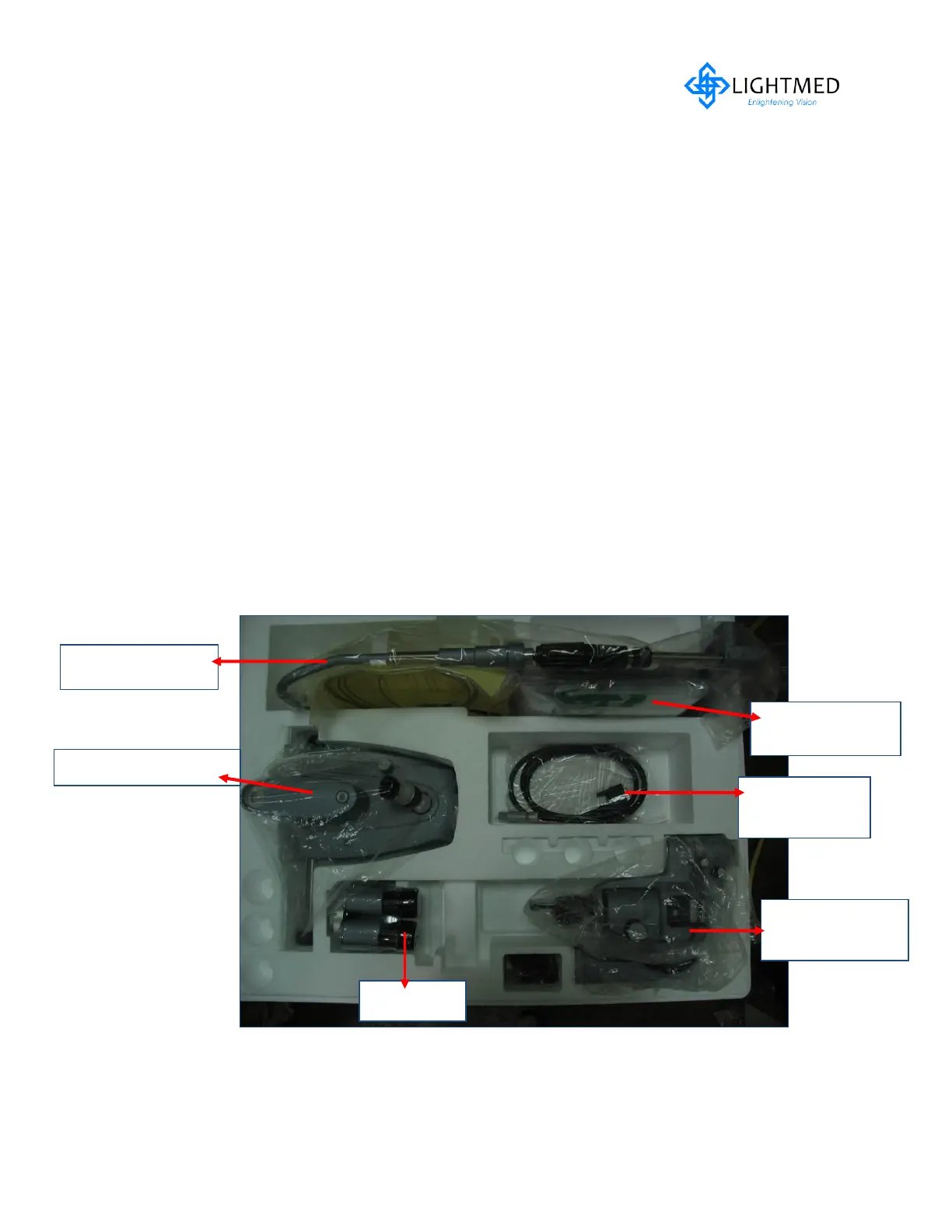
Figure 5.7 Slit lamp Packaging Ass’y
 Loading...