TruScan 532 Single - Wavelength – Operators Manual Rev. No 02 Page 71 of 114
B. LDU Systems / LCD / Footswitch / Accessories
Three types of LDU system Lightmed supplying are:
Slit lamp (CSO980)
LIO
Endoprobes
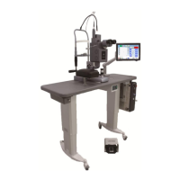
Slit lamp Integrated LDU (CSO980)
Prior to install the Slit lamp Integrated system, ensure all the corrected setup and
equipment are in placed to proceed the installation steps.
System Part(s):
Upper Arm Housing
Lower Base Housing
Magnifier Housing integrated with zoom pc and truscan
Binocular Ass’y
Accessories (cover, chinrest, and target rod)
Procedures:
1. Unpack all the packaging items from the cartoon box (refer to fig. 5.7)
2. Lay them over the fully assembled table ass’y and ensure the location is the final
destination and well level
3. Assemble the slit lamp upper arm and lower base housings together by fasten the
screw (refer to 5.8)
4. Carefully position the fully assembled slit lamp ass’y over the rail and gently slide
through the rails for the smoothness
5. Ensure the slit lamp ass’y is horizontally in parallel axis (realign if applicable) and the
cabling (slit lamp power / magnifier housing signal) out of way or not jammed (refer
to fig. 5.9)
6. Organize the cabling through the guide hole and strap Velcro tie underneath of the
table top (refer to fig. 5.10)
7. Plug in joystick cabling to the lower base housing
8. Place the gear cover ass'y
9. Glide the delivery housing with Truscan module integrated until it reaches to the
chrome stopper and gently secure the screw (refer to fig. 5.11a-b)
 Loading...