18 19
OVERVIEWINSTALLATION
PLANNING
SPEAKER LOCATION &
INSTALLATION
SET UP &
INTEGRATION
INSTALLING OPTIONAL
EQUIPMENT
TROUBLESHOOTING
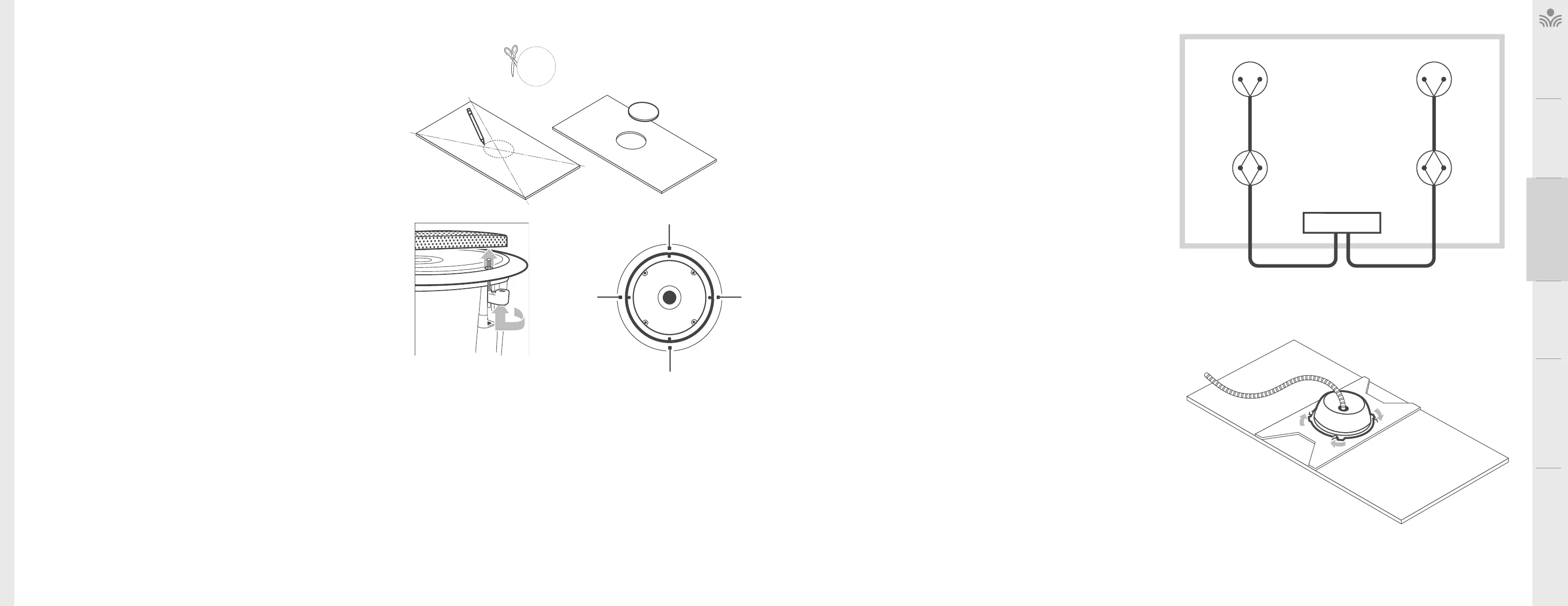
INSTALLING THE JCS SPEAKERS INTO THE CEILING TILE
Before beginning the speaker tile work, choose a flat work surface.
1. Using the straight edge, determine the center of each ceiling tile by drawing a
straight line from corner to corner on the back of the tile.
2. Using the center point, mark a 10’’ circle on the back of the tile.
NOTE: A circular template is included (see figure 1A, 1B).
3. Using a utility knife or jigsaw, cut out the circular hole in the center of the tile as
neatly as possible. The speaker bale will cover up some minor rough edges.
NOTE: To ensure the hole is large enough, cut slightly outside template lines (see
figure 1C).
4. Remove the speaker grille by turning and pushing one of the arms upward (see
figure 2).
5. Turn the tile on its side and insert the speaker into the front side of the tile and place
the tile bridge horizontally across the back of the tile. Holding the speaker and tile
bridge in place, start all four of the mounting screws. Use a screwdriver to tighten
the four mounting screws to secure the speaker, tile bridge and tile together.
6. Repeat steps 1 through 4 for each of the remaining speakers and tiles.
D.
MOUNTING
SCREWS
FIGURE A B C
” TILE HOLE TEMPLATE
FIGURE :
REMOVE THE GRILLE
FIGURE :
WIRING DIAGRAM
SPEAKER # SPEAKER #
SPEAKER # SPEAKER #
AMPLIFIER
Black
(-)
Black
(-)
Black
(-)
Black
(-)
Red
(+)
Red
(+)
Red
(+)
Red
(+)
30/50 . 30/50 .
50 . 50 .
CONNECTING AND ROUTING SPEAKER WIRE
Prep two conductor 18 awg plenum rated speaker wire ends for insertion into the
speaker connectors.
NOTE: it is advised to prep and connect each speaker at ground level.
1. Distribute the appropriate lengths of wire to each speaker (see figure 5). There
should be (2) 30 lengths of wire between two pairs of speakers. There should
be (2) 50 lengths of wire for home runs back to the amplifier.
2. Start with speaker #1 (see figure 4).
3. Remove a conduit knockout in the speaker enclosure and install a plenum-rated
low voltage pass-through or conduit hardware in the enclosure (not included).
4. Route the speaker wire through the conduit hardware and attach to the speaker
terminals by twisting the speaker wire and speaker pigtails together, securing
with the included wire nuts. Be sure to maintain proper polarity (see figure 5).
5. Install the speaker enclosure on the tile bridge securing it in place by turning the
enclosure clockwise (see figure 6).
6. Install speaker #1 with tile into the ceiling grid and route cabling (following local
building codes) to speaker #2.
Note: Building codes vary from state to state and county to county. It may be
required that the speaker itself be secured to a support wire.
7. Remove a conduit knockout in speaker #2’s enclosure and install a plenum-
rated low voltage pass-through or conduit hardware to the enclosure (not
included).
8. Route speaker #1 wire and speaker #2 wire (50 if ordered) through the conduit
hardware and attach to the speaker terminals by twisting the speaker wire
and speaker pigtails together, securing with the included wire nuts. Be sure to
maintain proper polarity (see Figure 5).
9. Install the speaker enclosure on the tile bridge securing it in place by turning the
enclosure clockwise (see Figure 6).
10. Install speaker #2 with tile into ceiling grid and route cabling (following local
building codes) to the receiver/amplifier.
11. Repeat steps 3 through 10 for speakers #3 and #4.
12. To continue with installation, go to Page 31 - Connecting Wire to Amplifier.
FIGURE :
SECURING THE ENCLOSURE